ADCMP604BKSZ-REEL7

ADCMP604/ADCMP605 Data Sheet
Parameter Symbol Conditions Min Typ Max Unit
AC PERFORMANCE
1
Rise Time/Fall Time t
R
, t
F
10% to 90% 600 ps
Propagation Delay t
PD
V
CCI
= V
CCO
= 2.5 V to 5.0 V,
V
OD
= 50 mV
1.6 ns
V
CCI
= V
CCO
= 2.5 V, V
OD
= 10 mV 3.0 ns
Propagation Delay SkewRising to Falling Transition t
PINSKEW
V
CCI
= V
CCO
= 2.5 V to 5.0 V 70 ps
Propagation Delay SkewQ to QB V
CCI
= V
CCO
= 2.5 V to 5.0 V 70 ps
Overdrive Dispersion 10 mV < V
OD
< 125 mV 1.6 ns
Common-Mode Dispersion V
CM
= −0.2 V to V
CCI
+ 0.2 V 250 ps
Input Bandwidth 500 MHz
Minimum Pulse Width
PW
MIN
V
CCI
= V
CCO
= 2.5 V to 5.0 V,
PW
OUT
= 90% of PW
IN
1.3
ns
POWER SUPPLY
Input Supply Voltage Range V
CCI
2.5 5.5 V
Output Supply Voltage Range V
CCO
2.5 5.0 V
Positive Supply Differential (ADCMP605) V
CCI
− V
CCO
Operating −3 +3 V
V
CCI
− V
CCO
Nonoperating 5.0 +5.0 V
Positive Supply Current (ADCMP604) I
VCCI/VCCO
V
CCI
= V
CCO
= 2.5 V to 5.0 V 15 21 mA
Input Section Supply Current (ADCMP605)
I
VCCI
V
CCI
= 2.5 V to 5.5 V
1.6
mA
Output Section Supply Current (ADCMP605) I
VCCO
V
CCO
= 2.5 V to 5.0 V 15 23 mA
Power Dissipation P
D
V
CCI
= V
CCO
= 2.5 V 37 55 mW
V
CCI
= V
CCO
= 5.0 V 95 120 mW
Power Supply Rejection Ratio PSRR V
CCI
= V
CCO
= 2.5 V to 5.0 V −50 dB
Shutdown Mode I
CCI
V
CCI
= V
CCO
= 2.5 V to 5.0 V 0.92 1.1 mA
Shutdown Mode I
CCO
V
CCI
= V
CCO
= 2.5 V to 5.0 V 30 +30 µA
1
V
IN
= 100 mV square input at 50 MHz, V
OD
= 50 mV, V
CM
= 1.25 V, V
CCI
= V
CCO
= 2.5 V, unless otherwise noted.
Rev. C | Page 4 of 14
Data Sheet ADCMP604/ADCMP605
TIMING INFORMATION
Figure 2 illustrates the ADCMP604/ADCMP605 latch timing relationships. Table 2 provides definitions of the terms shown in Figure 2.
1.1V
50%
V
N
± V
OS
DIFFERENTIAL
INPUT VOLTAGE
LATCH ENABLE
Q OUTPUT
t
H
t
PDL
t
PLOH
t
F
V
IN
V
OD
t
S
t
PL
50%
Q OUTPUT
t
PDH
t
PLOL
t
R
05916-025
Figure 2. System Timing Diagram
Table 2. Timing Descriptions
Symbol Timing Description
t
PDH
Input-to-Output High Delay Propagation delay measured from the time the input signal crosses the reference
(± the input offset voltage) to the 50% point of an output low-to-high transition.
t
PDL
Input-to-Output Low Delay Propagation delay measured from the time the input signal crosses the reference
(± the input offset voltage) to the 50% point of an output high-to-low transition.
t
PLOH
Latch Enable-to-Output High Delay
Propagation delay measured from the 50% point of the latch enable signal low-to-high
transition to the 50% point of an output low-to-high transition.
t
PLOL
Latch Enable-to-Output Low Delay Propagation delay measured from the 50% point of the latch enable signal low-to-high
transition to the 50% point of an output high-to-low transition.
t
H
Minimum Hold Time Minimum time after the negative transition of the latch enable signal that the input signal
must remain unchanged to be acquired and held at the outputs.
t
PL
Minimum Latch Enable Pulse Width Minimum time that the latch enable signal must be high to acquire an input signal change.
t
S
Minimum Setup Time Minimum time before the negative transition of the latch enable signal occurs that an
input signal change must be present to be acquired and held at the outputs.
t
R
Output Rise Time Amount of time required to transition from a low to a high output as measured at the
20% and 80% points.
t
F
Output Fall Time Amount of time required to transition from a high to a low output as measured at the
20% and 80% points.
V
OD
Voltage Overdrive Difference between the input voltages, V
A
and V
B
.
Rev. C | Page 5 of 14
ADCMP604/ADCMP605 Data Sheet
ABSOLUTE MAXIMUM RATINGS
Table 3.
Parameter Rating
Supply Voltages
Input Supply Voltage (V
CCI
to GND) 0.5 V to +6.0 V
Output Supply Voltage (V
CCO
to GND) 0.5 V to +6.0 V
Positive Supply Differential (V
CCI
V
CCO
) 6.0 V to +6.0 V
Input Voltages
Input Voltage 0.5 V to V
CCI
+ 0.5 V
Differential Input Voltage ±(V
CCI
+ 0.5 V)
Maximum Input/Output Current ±50 mA
Shutdown Control Pin
Applied Voltage (S
DN
to GND) 0.5 V to V
CCO
+ 0.5 V
Maximum Input/Output Current ±50 mA
Latch/Hysteresis Control Pin
Applied Voltage (HYS to GND)
0.5 V to V
CCO
+ 0.5 V
Maximum Input/Output Current ±50 mA
Output Current ±50 mA
Temperature
Operating Temperature Range, Ambient 40°C to +125°C
Operating Temperature, Junction 150°C
Storage Temperature Range 65°C to +150°C
Stresses at or above those listed under Absolute Maximum
Ratings may cause permanent damage to the product. This is a
stress rating only; functional operation of the product at these
or any other conditions above those indicated in the operational
section of this specification is not implied. Operation beyond
the maximum operating conditions for extended periods may
affect product reliability.
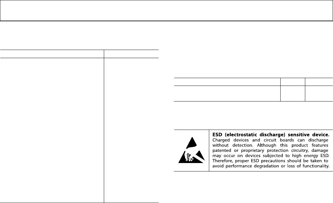
THERMAL RESISTANCE
θ
JA
is specified for the worst-case conditions, that is, a device
soldered in a circuit board for surface-mount packages.
Table 4. Thermal Resistance
Package Type θ
JA
1
Unit
6-Lead SC70 (KS-6) 426 °C/W
12-Lead LFCSP_VQ (CP-12-1)
62
°C/W
1
Measurement in still air.
ESD CAUTION
Rev. C | Page 6 of 14

ADCMP604BKSZ-REEL7

Mfr. #:
Manufacturer:
Analog Devices Inc.
Description:
Analog Comparators RR Fast 2.5-5.5V SGL-Supply LVDS
Lifecycle:
New from this manufacturer.
Delivery:
DHL FedEx Ups TNT EMS
Payment:
T/T Paypal Visa MoneyGram Western Union