4©2017 Integrated Device Technology, Inc. December 1, 2017
9ZML1233E / 9ZML1253E Datasheet
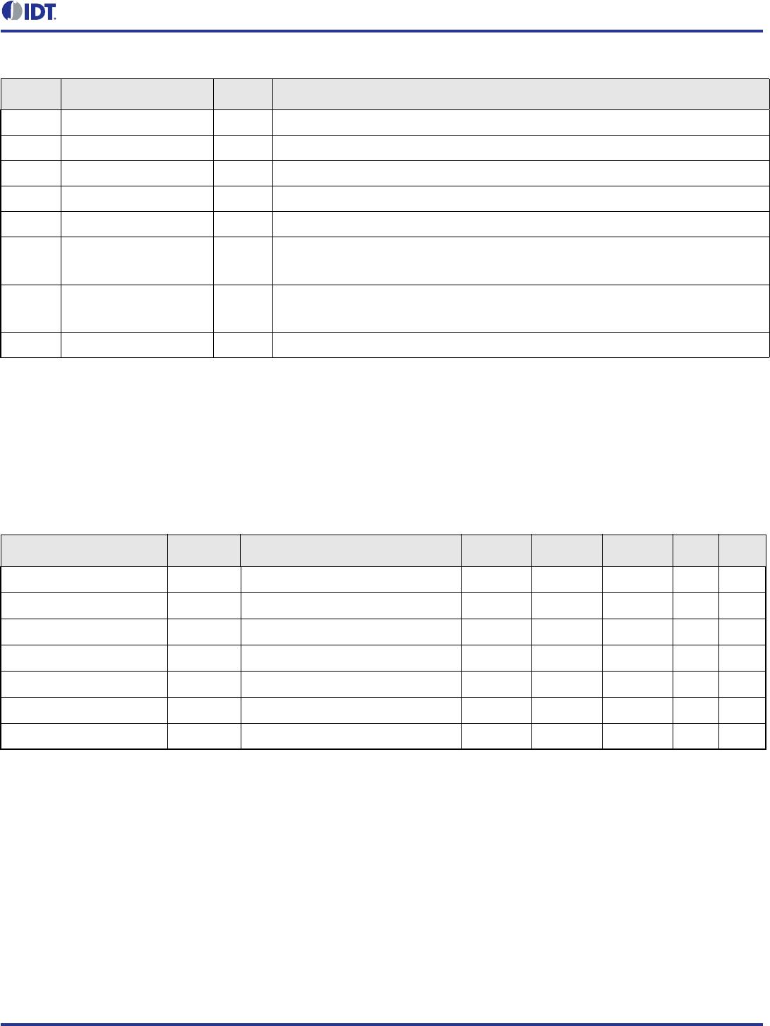
37 ^OE4# Input
Active low input for enabling output 4. This pin has an internal pull-up resistor.
1 = disable outputs, 0 = enable outputs.
38 ^OE5# Input
Active low input for enabling output 5. This pin has an internal pull-up resistor.
1 = disable outputs, 0 = enable outputs.
39 GND GND Ground pin.
40 V
DDIO
Power Power supply for differential outputs.
41 DIF_4 Output HCSL true clock output.
42 DIF_4# Output HCSL complementary clock output.
43 DIF_5 Output HCSL true clock output.
44 DIF_5# Output HCSL complementary clock output.
45 V
DD
PWR Power supply, nominally 3.3V.
46 GND GND Ground pin.
47 DIF_6 Output HCSL true clock output.
48 DIF_6# Output HCSL complementary clock output.
49 DIF_7 Output HCSL true clock output.
50 DIF_7# Output HCSL complementary clock output.
51 GND GND Ground pin.
52 V
DDIO
Power Power supply for differential outputs.
53 ^OE6# Input
Active low input for enabling output 6. This pin has an internal pull-up resistor.
1 = disable outputs, 0 = enable outputs.
54 ^OE7# Input
Active low input for enabling output 7. This pin has an internal pull-up resistor.
1 = disable outputs, 0 = enable outputs.
55 ^OE8# Input
Active low input for enabling output 8. This pin has an internal pull-up resistor.
1 = disable outputs, 0 = enable outputs.
56 ^OE9# Input
Active low input for enabling output 9. This pin has an internal pull-up resistor.
1 = disable outputs, 0 = enable outputs.
57 NC — No connection.
58 GND GND Ground pin.
59 DIF_8 Output HCSL true clock output.
60 DIF_8# Output HCSL complementary clock output.
61 DIF_9 Output HCSL true clock output.
62 DIF_9# Output HCSL complementary clock output.
63 GND GND Ground pin.
64 V
DD
Power Power supply, nominally 3.3V.
65 DIF_10 Output HCSL true clock output.
Table 1. Pin Descriptions (Cont.)
Number Name Type Description