MAX5924/MAX5925/MAX5926
1V to 13.2V, n-Channel Hot-Swap Controllers
Require No Sense Resistor
10 ______________________________________________________________________________________
LOGIC
CONTROL
OSCILLATOR
TIMER
V
S
V
Z
= 9V
N
CHARGE PUMP
EN/(EN1***)
CB
SLEW
V
CC
GATE
V
CC
V
CC
V
CC
V
CC
PGOOD**
OUT
SC_DET
GND
0.8V
1.24V
EN2***
SENSE
LATCH***
PGOOD*
0.2V
*MAX5924B, MAX5924D, MAX5925B, MAX5925D, MAX5926 ONLY.
**MAX5924A, MAX5924C, MAX5925A, MAX5925C, MAX5926 ONLY.
***MAX5926 ONLY.
TC***
SLOW
COMPARATOR
FAST
COMPARATOR
R
LP
R
CBF
V
CB,TH
V
CBF,TH
I
CB
MAX5924
MAX5925
MAX5926
N
2µA
A
75k
75k
50k
Figure 3. Functional Diagram
MAX5924/MAX5925/MAX5926
1V to 13.2V, n-Channel Hot-Swap Controllers
Require No Sense Resistor
______________________________________________________________________________________ 11
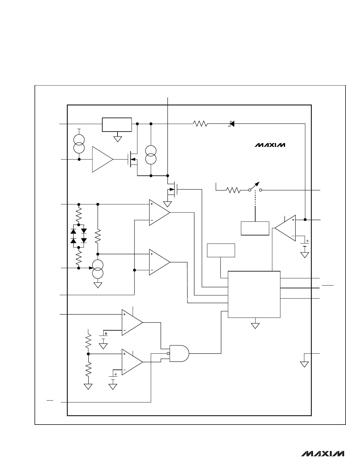
Detailed Description
The MAX5924/MAX5925/MAX5926 are hot-swap con-
troller ICs designed for applications where a line card is
inserted into a live backplane. Normally, when a line card
is plugged into a live backplane, the card’s discharged
filter capacitors provide a low impedance that can
momentarily cause the main power supply to collapse.
The MAX5924/MAX5925/MAX5926 are designed to
reside either in the backplane or in the removable card
to provide inrush current limiting and short-circuit pro-
tection. This is achieved using an external n-channel
MOSFET and an optional external current-sense resistor.
Several critical parameters can be configured:
Slew rate (inrush current)
Circuit-breaker threshold
Turn-on voltage
Fault-management mode (MAX5926)
Circuit-breaker temperature coefficient (MAX5926)
See the
Selector Guide
for a device-specific list of fac-
tory-preset features and parameters.
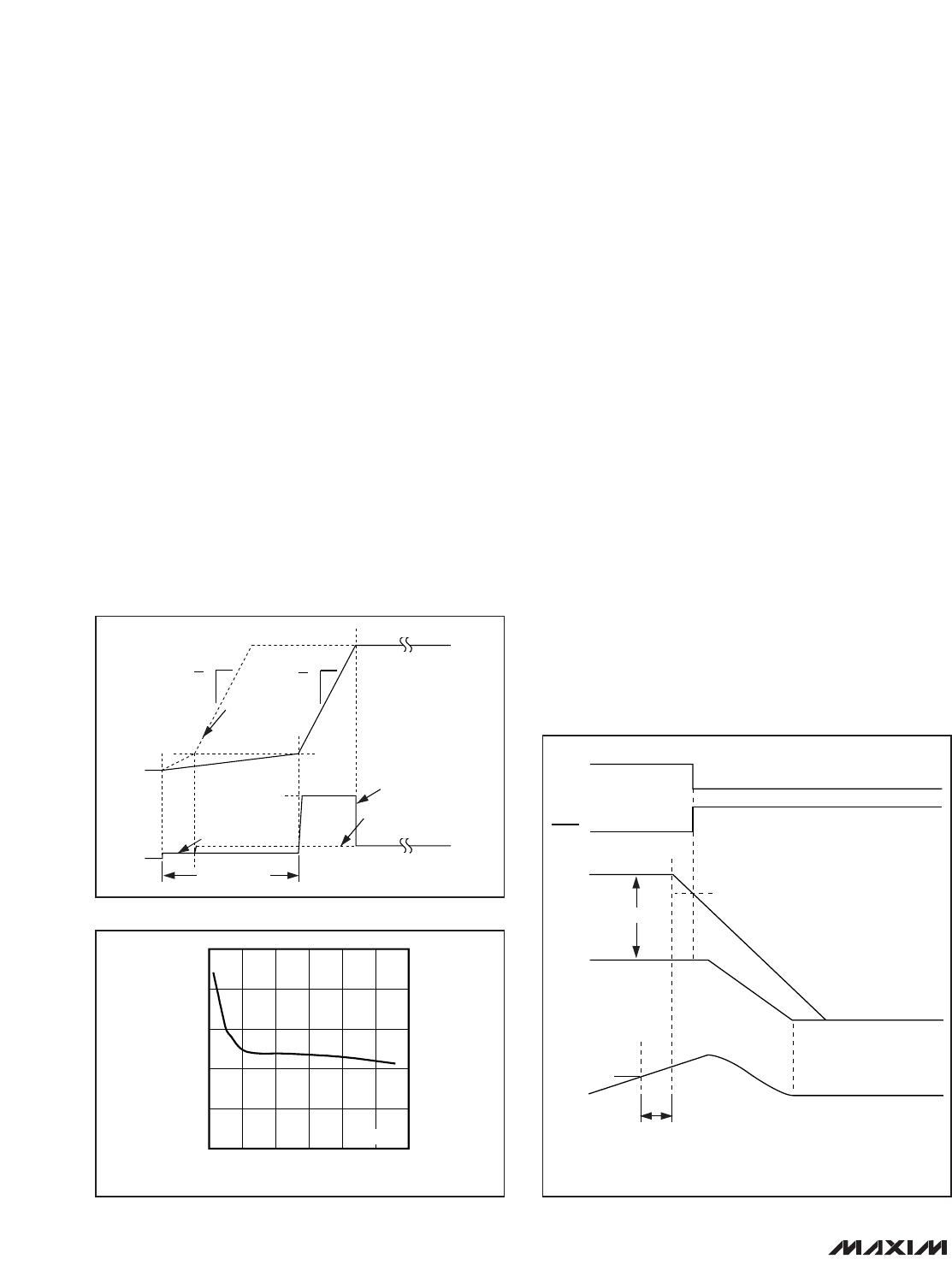
Startup Mode
It is important that both V
CC
and V
S
rise at a minimum
rate of 100mV/ms during the critical time when power
voltages are below those values required for proper
logic control of internal circuitry. This applies for 0.5V
V
CC
2.5V and 0.5V V
S
0.8V. This is particularly
true when LATCH is tied high.
The MAX5924/MAX5925/MAX5926 control an external
MOSFET placed in the positive power-supply pathway.
When power is first applied, the MAX5924/MAX5925/
MAX5926 hold the MOSFET off indefinitely if the supply
voltage is below the undervoltage lockout level or if the
device is disabled (see the
EN (MAX5924/MAX5925),
EN1/EN2 (MAX5926)
section). If neither of these condi-
tions exist, the device enters a UVLO startup delay
period for 200ms. Next, the MAX5924/MAX5925/
MAX5926 detect whether an external sense resistor is
present; and then autoconfigure accordingly (see
Figure 4).
If no sense resistor is present, bilevel fault protection
is disabled and load-probing circuitry is enabled
(see the
Load Probing
section).
If load probing is not successful, the fault is man-
aged according to the selected fault management
mode (see the
Latched and Auto-Retry Fault
Management
section).
If load probing (see the
Load Probing
section) is suc-
cessful, slew-rate limiting is employed to gradually
turn on the MOSFET.
If the device detects an external R
SENSE
, circuit-
breaker threshold is set at 2xI
CB
, the slow compara-
tor is disabled, the startup phase begins without
delay for load probing, and slew-rate limiting is
employed to gradually turn on the MOSFET.
During the startup phase, the voltage at the load, V
OUT
,
rises at a rate determined by the selected slew rate (see
the
Slew Rate
section). The inrush current, I
INRUSH
, to
the load is limited to a level proportional to the load
capacitance, C
L
, and the slew rate:
where SR is the slew rate in V/ms and C
L
is load capac-
itance in µF.
For operation with and without R
SENSE
, once V
GATE
-
V
OUT
exceeds V
CB,EN
, PGOOD and/or PGOOD
assert. When V
GATE
- V
OUT
= V
CB,EN
, the MAX5924/
MAX5925/MAX5926 enable standard bilevel fault pro-
tection with normal I
CB
(see the
Bilevel Fault Protection
section).
I
CSR
INRUSH
L
=
×
1000
V
CC
RISES ABOVE V
UVLO
ENABLE TRUE?
UVLO 200ms DELAY
V
GS
V
THPGOOD
FAULT MANAGEMENT
DISABLE FAULT PROTECTION,
ENABLE LOAD PROBE
SLEW-RATE-LIMITED
STARTUP
R
SENSE
PRESENT?
V
GS
V
CB,EN
NO
NO
NO
PGOOD
YES
NO
YES
YES
YES
LOAD PROBE
SUCCESSFUL?
ENABLE STANDARD BILEVEL
FAULT PROTECTION
BEGIN NORMAL OPERATION
I
CB,SU
= 2 x I
CB
DISABLE SLOW
COMPARATOR
Figure 4. Startup Flow Chart
MAX5924/MAX5925/MAX5926
1V to 13.2V, n-Channel Hot-Swap Controllers
Require No Sense Resistor
12 ______________________________________________________________________________________
Load Probing
The MAX5924/MAX5925/MAX5926 load-probing circuit-
ry detects short-circuit conditions during startup. Load
probing is active only when no external R
SENSE
is
detected. As the device begins load probing, SC_DET
is connected to V
CC
through an internal switch with an
on-resistance of R
LP
(Figure 6). V
CC
then charges the
load with a probe current limited at 200mA.
I
PROBE
= (V
CC
- V
OUT
)/(R
LP
+ R
SC
) (Figure 1)
If the load voltage does not reach V
LP,TH
(0.2V typ)
within t
LP
, a short-circuit fault is detected and the start-
up mode is terminated according to the selected fault-
management mode (see the
Fault Management
section
and Figure 5). If no fault condition is present,
PGOOD/PGOOD asserts at the end of the startup peri-
od (see the Turn-On Waveforms in the
Typical
Operating Characteristics
).
Load probing can only be, and must be, employed
when not using an external R
SENSE
.
Normal Operation
In normal operation, after startup is complete, protec-
tion is provided by turning off the external MOSFET
when a fault condition is encountered. Dual-speed/
bilevel fault protection incorporates two comparators
with different thresholds and response times to monitor
the current:
1) Slow comparator. This comparator has a 1.6ms
(typ) response time. The slow comparator ignores
low-amplitude momentary current glitches. After an
extended overcurrent condition, a fault is acknowl-
edged and the MOSFET gate is discharged.
2) Fast comparator. This comparator has a quick
response time and a higher threshold voltage. The
fast comparator turns off the MOSFET immediately
when it detects a large high-current event such as a
short circuit.
In each case, when a fault is encountered, the power-
good output deasserts and the device drives GATE low.
After a fault, the MAX5924A, MAX5924B, MAX5925A,
and MAX5925B latch GATE low and the MAX5924C,
MAX5924D, MAX5925C, and MAX5925D enter the
autoretry mode. The MAX5926 has selectable latched or
autoretry modes. Figure 7 shows the slow comparator
response to an overcurrent fault.
V
CC
(V)
R
LP
()
1210864
6
8
10
12
14
4
214
V
CC
= V
S
Figure 6. Load-Probe Resistance vs. Supply Voltage
V
GATE
PGOOD*
V
OUT
I
LOAD
I
LIM
3.0V TO 6.7V
PGOOD**
*MAX5924B, MAX5924D, MAX5925B, MAX5925D, AND MAX5926 ONLY.
**MAX5924A, MAX5924C, MAX5925A, MAX5925C, AND MAX5926 ONLY.
t
CBS
V
THPGOOD
Figure 7. Slow Comparator Response to an Overcurrent Fault
t
PROBE
< t
LP
I
INRUSH
C
L
= LARGE
C
L
= SMALL
V
OUT
V
OUT
I
LOAD
I
LOAD
I
PROBE
V
LP,TH
(0.2V typ)
SR = dV
dt
C
L
= SMALL
SR = dV
dt
Figure 5. Startup Waveform

MAX5924BEUB+

Mfr. #:
Manufacturer:
Maxim Integrated
Description:
Hot Swap Voltage Controllers 1-13.2V Hot-Swap Controller
Lifecycle:
New from this manufacturer.
Delivery:
DHL FedEx Ups TNT EMS
Payment:
T/T Paypal Visa MoneyGram Western Union