MAX5924/MAX5925/MAX5926
1V to 13.2V, n-Channel Hot-Swap Controllers
Require No Sense Resistor
______________________________________________________________________________________ 17
Circuit-Breaker Temperature Coefficient
In applications where the external MOSFET’s on-resis-
tance is used as a sense resistor to determine overcur-
rent conditions, a 3300ppm/°C temperature coefficient
is desirable to compensate for the R
DS(ON)
tempera-
ture coefficient. Use the MAX5926’s TC input to select
the circuit-breaker programming current’s temperature
coefficient, TC
ICB
(see Table 2). The MAX5924 temper-
ature coefficient is preset to 0ppm/°C, and the
MAX5925’s is preset to 3300ppm/°C.
Setting TC
ICB
to 3300ppm/°C allows the circuit-breaker
threshold to track and compensate for the increase in the
MOSFET’s R
DS(ON)
with increasing temperature. Most
MOSFETs have a temperature coefficient within a
3000ppm/°C to 7000ppm/°C range. Refer to the MOSFET
data sheet for a device-specific temperature coefficent.
R
DS(ON)
and I
CB
are temperature dependent, and can
therefore be expressed as functions of temperature. At
a given temperature, the MAX5925/MAX5926 indicate
an overcurrent condition when:
I
TRIPSLOW
x R
DS(ON)
(T) ≥ I
CB
(T) x R
CB
+ |V
CB,
OS
|
where V
CB,OS
is the worst-case offset voltage. Figure 14
graphically portrays operating conditions for a MOSFET
with a 4500ppm/°C temperature coefficient.
Applications Information
Component Selection
n-Channel MOSFET
Most circuit component values may be calculated with
the aid of the MAX5924–MAX5926. The "Design calcula-
tor for choosing component values" software can be
downloaded from the MAX5924–MAX5926 Quickview on
the Maxim website.
Select the external n-channel MOSFET according to the
application’s current and voltage level. Table 3 lists some
recommended components. Choose the MOSFET’s
on-resistance, R
DS(ON)
, low enough to have a minimum
voltage drop at full load to limit the MOSFET power dis-
sipation. High R
DS(ON)
can cause undesired power
loss and output ripple if the board has pulsing loads or
triggers an external undervoltage reset monitor at full
load. Determine the device power-rating requirement to
accommodate a short circuit on the board at startup
with the device configured in autoretry mode
.
Using the MAX5924/MAX5925/MAX5926 in latched mode
allows the consideration of MOSFETs with higher R
DS(ON)
and lower power ratings. A MOSFET can typically with-
stand single-shot pulses with higher dissipation than the
specified package rating. Low MOSFET gate capaci-
tance is not necessary since the inrush current limiting is
achieved by limiting the gate dv/dt. Table 4 lists some
recommended manufacturers and components.
Be sure to select a MOSFET with an appropriate gate
drive (see the
Typical Operating Characteristics
).
Typically, for V
CC
less than 3V, select a 2.5V V
GS
MOSFET.
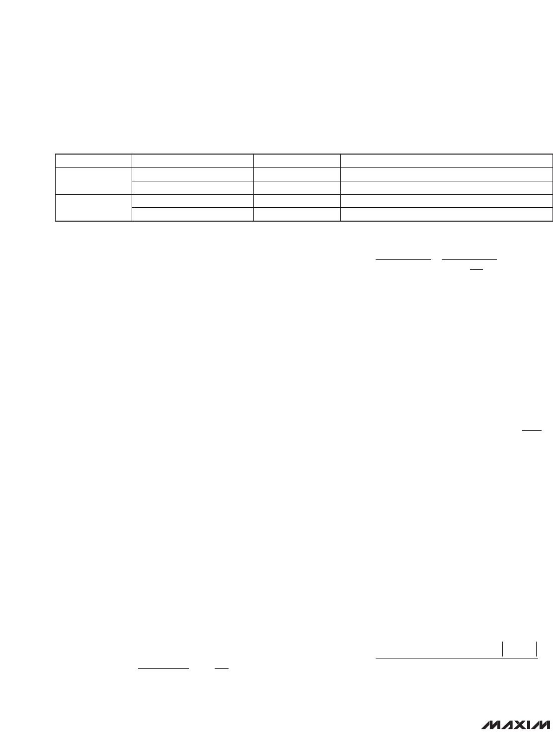
Table 2. Programming the Temperature
Coefficient (MAX5926)