DS3234
Extremely Accurate SPI Bus RTC with
Integrated Crystal and SRAM
16 ____________________________________________________________________
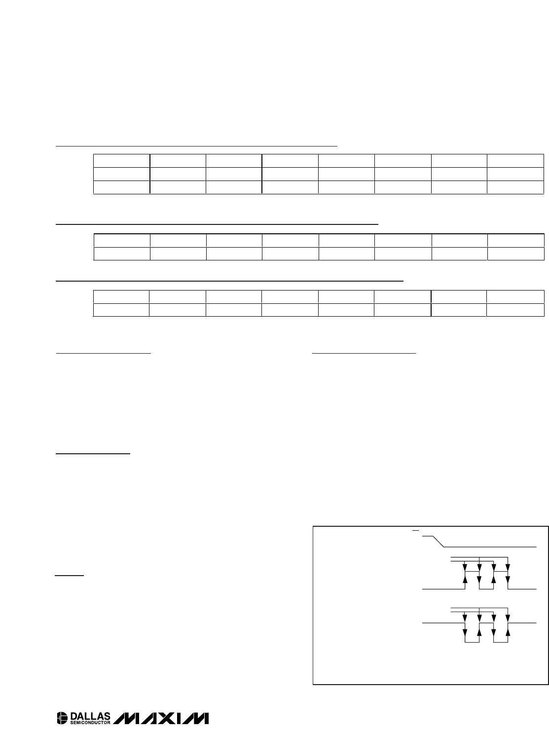
Aging Offset Register (10h/90h)
The aging offset register takes a user-provided value to
add to or subtract from the oscillator capacitor array.
The data is encoded in two’s complement, with bit 7
representing the SIGN bit. One LSB represents the
smallest capacitor to be switched in or out of the
capacitance array at the crystal pins. The aging offset
register capacitance value is added or subtracted from
the capacitance value that the device calculates for
each temperature compensation. The offset register is
added to the capacitance array during a normal tem-
perature conversion, if the temperature changes from
the previous conversion, or during a manual user con-
version (setting the CONV bit). To see the effects of the
aging register on the 32kHz output frequency immedi-
ately, a manual conversion should be performed after
each aging offset register change.
Positive aging values add capacitance to the array,
slowing the oscillator frequency. Negative values
remove capacitance from the array, increasing the
oscillator frequency.
The change in ppm per LSB is different at different tem-
peratures. The frequency vs. temperature curve is shift-
ed by the values used in this register. At +25°C, one
LSB typically provides about 0.1ppm change in fre-
quency. These bits are all set to logic 0 when power is
first applied.
Use of the aging register is not needed to achieve the
accuracy as defined in the EC tables, but could be
used to help compensate for aging at a given tempera-
ture. See the
Typical Operating Characteristics
section
for a graph showing the effect of the register on accu-
racy over temperature.
Temperature Registers (11h–12h)
Temperature is represented as a 10-bit code with a res-
olution of 0.25°C and is accessible at location 11h and
12h. The temperature is encoded in two’s complement
format, with bit 7 in the MSB representing the SIGN bit.
The upper 8 bits, the integer portion, are at location 11h
and the lower 2 bits, the fractional portion, are in the
upper nibble at location 12h. Example: 00011001 01b =
+25.25°C. Upon power reset, the registers are set to a
default temperature of 0°C and the controller starts a
temperature conversion.
The temperature is read on initial application of V
CC
and once every 64 seconds afterwards. The tempera-
ture registers are updated after each user-initiated con-
version and on every 64-second conversion. The
temperature registers are read-only.
BIT 7 BIT 6 BIT 5 BIT 4 BIT 3 BIT 2 BIT 1 BIT 0
NAME:
SIGN DATA DATA DATA DATA DATA DATA DATA
POR*:
00000000
Aging Offset (10h/90h)
BIT 7 BIT 6 BIT 5 BIT 4 BIT 3 BIT 2 BIT 1 BIT 0
NAME:
SIGN DATA DATA DATA DATA DATA DATA DATA
POR*:
00000000
Temperature Register (MSB) (11h)
BIT 7 BIT 6 BIT 5 BIT 4 BIT 3 BIT 2 BIT 1 BIT 0
NAME:
DATA DATA 0 0 0 0 0 0
POR*:
00000000
Temperature Register (LSB) (12h)
*
POR is defined as the first application of power to the device, either V
BAT
or V
CC
.
DS3234
Extremely Accurate SPI Bus RTC with
Integrated Crystal and SRAM
____________________________________________________________________ 17
Temperature Control
Register (13h/93h)
Bit 0: Battery-Backed Temperature Conversion
Disable (BB_TD). The battery-backed tempconv dis-
able bit prevents automatic temperature conversions
when the device is powered by the V
BAT
supply. This
reduces the battery current at the expense of frequen-
cy accuracy.
SRAM Address Register
(18h/98h)
The SRAM address register provides the 8-bit address
of the 256-byte memory array. The desired memory
address should be written to this register before the
data register is accessed. The contents of this register
are incremented automatically if the data register is
accessed more than once during a single transfer.
When the contents of the address register reach 0FFh,
the next access causes the register to roll over to 00h.
SRAM Data Register (19h/99h)
The SRAM data register provides the data to be written
to or the data read from the 256-byte memory array.
During a read cycle, the data in this register is that
found in the memory location in the SRAM address reg-
ister (18h/98h). During a write cycle, the data in this reg-
ister is placed in the memory location in the SRAM
address register (18h/98h). When the SRAM data regis-
ter is read or written, the internal register pointer
remains at 19h/99h and the SRAM address register
increments after each byte that is read or written, allow-
ing multibyte transfers.
SPI Serial Data Bus
The DS3234 provides a 4-wire SPI serial data bus to com-
municate in systems with an SPI host controller. The
DS3234 supports both single byte and multiple byte data
transfers for maximum flexibility. The DIN and DOUT pins
are the serial data input and output pins, respectively.
The CS input is used to initiate and terminate a data
transfer. The SCLK pin is used to synchronize data move-
ment between the master (microcontroller) and the slave
devices (see Table 3). The shift clock (SCLK), which is
generated by the microcontroller, is active only during
address and data transfer to any device on the SPI bus.
Input data (DIN) is latched on the internal strobe edge
and output data (DOUT) is shifted out on the shift edge
(Figure 2). There is one clock for each bit transferred.
Address and data bits are transferred in groups of eight.
BIT 7
BIT 6 BIT 5 BIT 4 BIT 3 BIT 2 BIT 1 BIT 0
NAME:
0
0 0 0 0 0 0 BB_TD
POR*:
0
0000000
Temperature Control (13h/93h)
BIT 7 BIT 6 BIT 5 BIT 4 BIT 3 BIT 2 BIT 1 BIT 0
NAME:
A7 A6 A5 A4 A2 A1 A1 A0
SRAM Address (18h/98h)
BIT 7 BIT 6 BIT 5 BIT 4 BIT 3 BIT 2 BIT 1 BIT 0
NAME:
D7 D6 D5 D4 D2 D1 D1 D0
SRAM Data (19h/99h)
CS
SCLK WHEN CPOL = 0
SCLK WHEN CPOL = 1
DATA LATCH (WRITE/INTERNAL STROBE)
SHIFT DATA OUT (READ)
DATA LATCH (WRITE/INTERNAL STROBE)
SHIFT DATA OUT (READ)
NOTE 1: CPHA BIT POLARITY (IF APPLICABLE) MAY NEED TO BE SET ACCORDINGLY.
NOTE 2: CPOL IS A BIT SET IN THE MICROCONTROLLER'S CONTROL REGISTER.
NOTE 3: DOUT REMAINS AT HIGH IMPEDANCE UNTIL 8 BITS OF DATA ARE READY TO BE
SHIFTED OUT DURING A READ.
Figure 2. Serial Clock as a Function of Microcontroller Clock-
Polarity Bit
Note: These registers do not default to any specific value.
*POR is defined as the first application of power to the device, either V
BAT
or V
CC
.
DS3234
Extremely Accurate SPI Bus RTC with
Integrated Crystal and SRAM
18 ____________________________________________________________________
Address and data bytes are shifted MSB first into the
serial data input (DIN) and out of the serial data output
(DOUT). Any transfer requires the address of the byte
to specify a write or read, followed by one or more
bytes of data. Data is transferred out of the DOUT pin
for a read operation and into the DIN for a write opera-
tion (Figures 3 and 4).
The address byte is always the first byte entered after
CS is driven low. The most significant bit of this byte
determines if a read or write takes place. If the MSB is
0, one or more read cycles occur. If the MSB is 1, one
or more write cycles occur.
MODE
CS
SCLK DIN DOUT
Disable H
Input Disabled Input Disabled High Impedance
*CPOL = 1, SCLK Rising
Write L
CPOL = 0, SCLK Falling
Data Bit Latch High Impedance
CPOL = 1, SCLK Falling
Read L
CPOL = 0, SCLK Rising
X Next Data Bit Shift**
Read Invalid Location L Don’t Care
Don’t Care High Impedance
Table 3. SPI Pin Function
R/W
A6 A5 A4 A3 A2 A1 A0 D7 D6 D5 D4 D3 D2 D1 D0
CS
SCLK
DIN
DOUT
HIGH IMPEDANCE
Figure 3. SPI Single-Byte Write
A6 A5 A4 A3 A2 A1 A0
D7 D6 D5 D4 D3 D2 D1 D0
CS
SCLK
DIN
DOUT
HIGH IMPEDANCE
R/W
Figure 4. SPI Single-Byte Read
*
CPOL is the clock-polarity bit set in the control register of the host microprocessor.
**
DOUT remains at high impedance until 8 bits of data are ready to be shifted out during a read.

DS3234S#

Mfr. #:
Manufacturer:
Maxim Integrated
Description:
Real Time Clock Integrated RTC/TCXO/Crystal
Lifecycle:
New from this manufacturer.
Delivery:
DHL FedEx Ups TNT EMS
Payment:
T/T Paypal Visa MoneyGram Western Union

Products related to this Datasheet