IDT
®
Nineteen Output Differential Buffer for PCIe Gen3
9DB1933
Nineteen Output Differential Buffer for PCIe Gen3
4
1676A—07/12/10
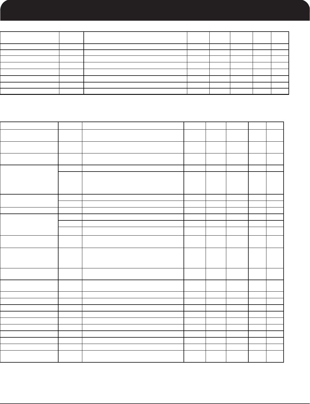
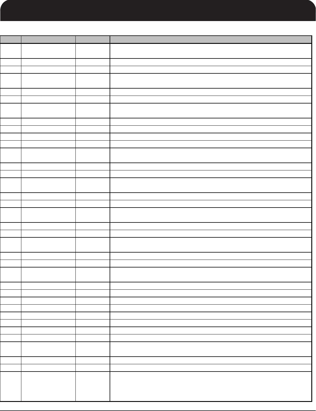
Pin Description (cont.)
PIN # PIN NAME PIN TYPE DESCRIPTION
37 OE9# IN
Active low input for enabling DIF pair 9.
1 =disable outputs, 0 = enable outputs
38
DIF_9
OUT
0.7V differential true clock output
39 DIF_9# OUT 0.7V differential Complementary clock output
40 OE10# IN
Active low input for enabling DIF pair 10.
1 =disable outputs, 0 = enable outputs
41
DIF_10
OUT
0.7V differential true clock output
42 DIF_10# OUT 0.7V differential Complementary clock output
43 OE11# IN
Active low input for enabling DIF pair 11.
1 =disable outputs, 0 = enable outputs
44
DIF_11
OUT
0.7V differential true clock output
45 DIF_11# OUT 0.7V differential Complementary clock output
46 GND PWR Ground pin.
47 VDD PWR Power supply, nominal 3.3V
48 OE12# IN
Active low input for enabling DIF pair 12.
1 =disable outputs, 0 = enable outputs
49 DIF_12 OUT 0.7V differential true clock output
50 DIF_12# OUT 0.7V differential Complementary clock output
51 OE13# IN
Active low input for enabling DIF pair 13.
1 =disable outputs, 0 = enable outputs
52 DIF_13 OUT 0.7V differential true clock output
53 DIF_13# OUT 0.7V differential Complementary clock output
54 OE14# IN
Active low input for enabling DIF pair 14.
1 =disable outputs, 0 = enable outputs
55 DIF_14 OUT 0.7V differential true clock output
56 DIF_14# OUT 0.7V differential Complementary clock output
57 CKPWRGD/PD# IN
A rising edge samples latched inputs and release Power Down Mode, a low
puts the part into power down mode and tristates all outputs.
58 DIF_15 OUT 0.7V differential true clock output
59 DIF_15# OUT 0.7V differential Complementary clock output
60 OE_15_16# IN
Active low input for enabling DIF pair 15 and 16.
1 = tri-state outputs, 0 = enable outputs
61 DIF_ 16 OUT 0.7V differential true clock output
62 DIF_16# OUT 0.7V differential Complementary clock output
63
VDD
PWR
Power supply, nominal 3.3V
64 GND PWR Ground pin.
65 DIF_17 OUT 0.7V differential true clock output
66 DIF_17# OUT 0.7V differential Complementary clock output
67
DIF_18
OUT
0.7V differential true clock output
68 DIF_18# OUT 0.7V differential Complementary clock output
69 OE_17_18# IN
Active low input for enabling DIF pair 17, 18.
1 = tri-state outputs, 0 = enable outputs
70
DIF_IN
IN
0.7 V Differential TRUE input
71 DIF_IN# IN 0.7 V Differential Complementary Input
72 SMB_A2_PLLBYP# IN
SMBus address bit 2. When Low, the part operates as a fanout buffer with the
PLL bypassed. When High, the part operates as a zero-delay buffer (ZDB) with
the PLL operating.
0 = fanout mode (PLL bypassed), 1 = ZDB mode (PLL used)
IDT
®
Nineteen Output Differential Buffer for PCIe Gen3
9DB1933
Nineteen Output Differential Buffer for PCIe Gen3
5
1676A—07/12/10
Electrical Characteristics - Absolute Maximum Ratings
PARAMETER SYMBOL CONDITIONS
MIN TYP MAX
UNITS NOTES
3.3V Core Supply Voltage VDDA 4.6 V 1,2
3.3V Logic Supply Voltage VDD 4.6 V 1,2
Input Low Voltage V
IL
GND-0.5 V 1
Input High Voltage V
IH
Except for SMBus interface V
DD
+0.5V V 1
Input High Voltage V
IHSMB
SMBus clock and data pins 5.5V V 1
Storage Temperature Ts -65 150
°
C
1
Junction Temperature Tj 125 °C 1
Input ESD protection
ESD prot Human Body Model 2000 V 1
1
Guaranteed by design and characterization, not 100% tested in production.
2
Operation under these conditions is neither implied nor guaranteed.
Electrical Characteristics - Input/Supply/Common Parameters
TA = T
COM
;
Supply Voltage VDD = 3.3 V +/-5%
PARAMETER SYMBOL CONDITIONS MIN TYP MAX UNITS NOTES
Ambient Operating
Temperature
T
COM
Commmercial range 0 70 °C
1
Input High Voltage V
IH
Single-ended inputs, except SMBus, low
threshold and tri-level inputs
2 V
DD
+ 0.3 V 1
Input Low Voltage V
IL
Single-ended inputs, except SMBus, low
threshold and tri-level inputs
GND
- 0.3 0.8 V 1
I
IN
Single-ended inputs, V
IN
= GND, V
IN
= VDD -5 5 uA 1
I
INP
Single-ended inputs
V
IN
= 0 V; Inputs with internal pull-up resistors
V
IN
= VDD; Inputs with internal pull-down resistors
-200 200 uA 1
Input Frequency F
ibyp
V
DD
= 3.3 V, Bypass mode 10 166 MHz 2
F
ipll
V
DD
= 3.3 V, 100MHz PLL mode 90 100 110 MHz 2
Pin Inductance L
pin
7 nH 1
C
IN
Logic Inputs, except DIF_IN 1.5 5 pF 1
C
INDIF_IN
DIF_IN differential clock inputs 1.5 2.7 pF 1,4
C
OUT
Output pin capacitance 2.5 6 pF 1
Clk Stabilization T
STAB
From V
DD
Power-Up and after input clock
stabilization or de-assertion of PD# to 1st clock
1.000 1.8 ms 1,2
Input SS Modulation
Frequency
f
MODIN
Allowable Frequency
(Triangular Modulation)
30 33 kHz 1
OE# Latency t
LATOE#
DIF start after OE# assertion
DIF stop after OE# deassertion
4 12 cycles 1,3
Tdrive_PD# t
DRVPD
DIF output enable after
PD# de-assertion
300 us 1,3
Tfall t
F
Fall time of control inputs 5 ns 1,2
Trise t
R
Rise time of control inputs 5 ns 1,2
SMBus Input Low Voltage V
ILSMB
0.8 V 1
SMBus Input High Voltage V
IHSMB
2.1 V
DDSMB
V 1
SMBus Output Low Voltage V
OLSMB
@ I
PULLUP
0.4 V 1
SMBus Sink Current I
PULLUP
@ V
OL
4 mA 1
Nominal Bus Voltage V
DDSMB
3V to 5V +/- 10% 2.7 5.5 V 1
SCLK/SDATA Rise Time t
RSMB
(Max VIL - 0.15) to (Min VIH + 0.15) 1000 ns 1
SCLK/SDATA Fall Time t
FSMB
(Min VIH + 0.15) to (Max VIL - 0.15) 300 ns 1
SMBus Operating
Frequency
f
MAXSMB
Maximum SMBus operating frequency 100 kHz 1,5
1
Guaranteed by design and characterization, not 100% tested in production.
2
Control input must be monotonic from 20% to 80% of input swing.
5
The differential input clock must be running for the SMBus to be active
Input Current
3
Time from deassertion until outputs are >200 mV
4
DIF_IN input
Capacitance
IDT
®
Nineteen Output Differential Buffer for PCIe Gen3
9DB1933
Nineteen Output Differential Buffer for PCIe Gen3
6
1676A—07/12/10
Electrical Characteristics - Clock Input Parameters
TA = T
COM
or T
IND;
Supply Voltage VDD = 3.3 V +/-5%
PARAMETER SYMBOL CONDITIONS MIN TYP MAX UNITS NOTES
Input High Voltage - DIF_IN V
IHDIF
Differential inputs
(single-ended measurement)
600 800 1150 mV 1
Input Low Voltage - DIF_IN V
ILDIF
Differential inputs
(single-ended measurement)
V
SS
- 300 0 300 mV 1
Input Common Mode
Voltage - DIF_IN
V
COM
Common Mode Input Voltage 300 1000 mV 1
Input Amplitude - DIF_IN V
SWING
Peak to Peak value 300 1450 mV 1
Input Slew Rate - DIF_IN
dv/dt
Measured differentially
0.4
8
V/ns
1,2
Input Leakage Current I
IN
V
IN
= V
DD ,
V
IN
=
GND -5 5 uA 1
Input Duty Cycle d
tin
Measurement from differential wavefrom 45 55 % 1
Input Jitter - Cycle to Cycle J
DIFIn
Differential Measurement 0 125 ps 1
1
Guaranteed by design and characterization, not 100% tested in production.
2
Slew rate measured through +/-75mV window centered around differential zero
Electrical Characteristics - DIF 0.7V Current Mode Differential Outputs
T
A
= T
COM;
Supply Voltage VDD = 3.3 V +/-5%
PARAMETER SYMBOL CONDITIONS MIN TYP MAX UNITS NOTES
Slew rate
Trf
Scope averaging on
1
2
4
V/ns
1, 2, 3
Slew rate matching
Trf
Slew rate matching, Scope averaging on
20
%
1, 2, 4
Voltage High VHigh 660 789 850 1
Voltage Low VLow -150 45 150 1
Max Voltage
Vmax
834
1150
1
Min Voltage
Vmin
-300
17
1
Vswing
Vswing
Scope averaging off
300
744
mV
1, 2
Crossing Voltage (abs)
Vcross_abs
Scope averaging off
250
380
550
mV
1, 5
Crossing Voltage (var)
-Vcross
Scope averaging off 24 140 mV 1, 6
2
Measured from differential waveform
6
The total variation of all Vcross measurements in any particular system. Note that this is a subset of V_cross_min/max (V_cross absolute)
allowed. The intent is to limit Vcross induced modulation by setting V_cross_delta to be smaller than V_cross absolute.
mV
Statistical measurement on single-ended signal
using oscilloscope math function. (Scope averaging
on)
Measurement on single ended signal using absolute
value. (Scope averaging off)
mV
1
Guaranteed by design and characterization, not 100% tested in production. IREF = VDD/(3xR
R
). For R
R
= 475 (1%), I
REF
= 2.32mA. I
OH
=
6 x I
REF
and V
OH
= 0.7V @ Z
O
=50
(100 differential impedance).
3
Slew rate is measured through the Vswing voltage range centered around differential 0V. This results in a +/-150mV window around
differential 0V.
4
Matching applies to rising edge rate of Clock / falling edge rate of Clock#. It is measured in a +/-75mV window centered on the average
cross point where Clock rising meets Clock# falling. The median cross point is used to calculate the voltage thresholds the oscilloscope uses
for the edge rate calculations.
5
Vcross is defined as voltage where Clock = Clock# measured on a component test board and only applies to the differential rising edge (i.e.
Clock rising and Clock# falling).
Electrical Characteristics - Current Consumption
TA = T
COM;
Supply Voltage VDD = 3.3 V +/-5%
PARAMETER SYMBOL CONDITIONS MIN TYP MAX UNITS NOTES
Operating Supply Current I
DD3.3OP
All outputs active @100MHz, C
L
= Full load;
427 500
mA 1
Powerdown Current
I
DD3.3PDZ
All differential pairs tri-stated 32 40 mA 1
1
Guaranteed by design and characterization, not 100% tested in production.

9DB1933AKLF

Mfr. #:
Manufacturer:
IDT
Description:
Clock Buffer 19 OUTPUT PCIE GEN3 BUFFER
Lifecycle:
New from this manufacturer.
Delivery:
DHL FedEx Ups TNT EMS
Payment:
T/T Paypal Visa MoneyGram Western Union

Products related to this Datasheet