AD7376
Rev. D | Page 2 of 20
TABLE OF CONTENTS
Features .............................................................................................. 1
Applications ....................................................................................... 1
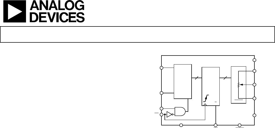
Functional Block Diagram .............................................................. 1
General Description ......................................................................... 1
Revision History ............................................................................... 2
Specifications ..................................................................................... 3
Electrical Characteristics—10 kΩ Version ................................ 3
Electrical Characteristics—50 kΩ, 100 kΩ Versions ............... 4
Timing Specifications .................................................................. 5
3-Wire Digital Interface ................................................................... 6
Absolute Maximum Ratings ............................................................ 7
ESD Caution .................................................................................. 7
Pin Configurations and Function Descriptions ........................... 8
Typical Performance Characteristics ............................................. 9
Theory of Operation ...................................................................... 12
Programming the Variable Resistor ......................................... 12
Programming the Potentiometer Divider ............................... 13
3-Wire Serial Bus Digital Interface .......................................... 13
Daisy-Chain Operation ............................................................. 14
ESD Protection ........................................................................... 14
Terminal Voltage Operating Range ......................................... 14
Power-Up and Power-Down Sequences .................................. 14
Layout and Power Supply Biasing ............................................ 15
Applications Information .............................................................. 16
High Voltage DAC ...................................................................... 16
Programmable Power Supply ................................................... 16
Audio Volume Control .............................................................. 17
Outline Dimensions ....................................................................... 18
Ordering Guide .......................................................................... 19
REVISION HISTORY
8/11—Rev. C to Rev. D
Changes to Output Logic Low Conditions, Table 1 ..................... 3
Changes to Output Logic Low Conditions, Table 2 ..................... 5
Changes to Figure 28 ...................................................................... 14
Updates Outline Dimensions ........................................................ 18
7/09—Rev. B to Rev. C
Changes to Features Section............................................................ 1
Updates Outline Dimensions ........................................................ 19
Changes to Ordering Guide .......................................................... 20
3/07—Rev. A to Rev. B
Updated Format .................................................................. Universal
Changes to Absolute Maximum Ratings ....................................... 7
Changes to ESD Protection Section ............................................. 14
Changes to Ordering Guide .......................................................... 19
11/05—Rev. 0 to Rev. A
Updated Format .................................................................. Universal
Deleted DIP Package .......................................................... Universal
Changes to Features ..........................................................................1
Separated Electrical Characteristics into Table 1 and Table 2 .....3
Separated Interface Timing into Table 3 ........................................5
Changes to Table 1 Through Table 3...............................................3
Added Table 4 ....................................................................................6
Added Figure 2...................................................................................6
Changes to Absolute Maximum Ratings Section ..........................7
Deleted Parametric Test Circuits Section .......................................7
Changes to Typical Performance Characteristics..........................9
Added Daisy-Chain Operation Section ...................................... 14
Added ESD Protection Section ..................................................... 14
Added Terminal Voltage Operating Range Section ................... 14
Added Power-Up and Power-Down Sequences Section ........... 14
Added Layout and Power Supply Biasing Section ..................... 15
Added Applications Section .......................................................... 16
Updated Outline Dimensions ....................................................... 18
Changes to Ordering Guide .......................................................... 19
10/97—Revision 0: Initial Version