© Semtech 2006 www.semtech.com
11
XE1202A TrueRF™
4.1.3 RSSI
When enabled, this function provides an RSSI (Received Signal Strength Indication) based on the signal at the
output of the base-band filter. To enable the RSSI function, the bit “RTParam_RSSI” should be set to “1” (see the
Configuration register section below). When enabled, the status of the RSSI is a 2-bit word stored in register
“DataOut_RSSI”, which can be read via the serial control interface. The contents of the register are defined in
Table 6 below, where V
RFFIL
is the differential amplitude of the equivalent input RF signal when the receiver is
operated in A-mode. The thresholds VTHRi are the thresholds at the output of the base-band filter divided by the
gain between the input of the receiver and this output.
DataOut_RSSI Description
0 0
V
RFFIL
VTHR1
0 1
VTHR1 < V
RFFIL
VTHR2
1 0
VTHR2 < V
RFFIL
VTHR3
1 1
VTHR3 < V
RFFIL
Table 6: RSSI status description
Two ranges, each of three VTHRi thresholds are defined and selected via the setting of the register
“RTParam_RSSR”, to provide an overall RSSI range of typically 25 dB.
The timing diagram of an RSSI measurement is illustrated by Figure 3 below. When the RSSI function has been
activated the signal strength is periodically measured and the result is stored in the register “DataOut_RSSI” at
each rising edge of DATAIN. TS_RS is the wake-up time required after the function has been enabled to ensure
that a valid reading of RSSI is obtained. For a proper operation, the pulse length on DATAIN has to be higher than
8µs.
xxx
val1 val2 val3 val4 0
val1 val4xxx
TS_RS
datain
RSSI_out
(internal signal)
/en
RTParam_RSSI
DtaOut_RSSI
TS_RSM
Figure 3: RSSI measurement timing diagram
For applications where a valid RSSI reading is required within as short a time frame as possible, enabling the RSSI
during receiver mode 010 instead of 100 (see the definition of TS_RS in Table 4) allows a valid RSSI within 1 ms of
valid data being received.
4.1.4 Frequency Error Indicator - FEI
When enabled, this function provides an indication of the frequency error of the local oscillator compared with the
received carrier frequency. For guaranteed operation of the FEI function, the following two conditions should be
satisfied.
© Semtech 2006 www.semtech.com
12
XE1202A TrueRF™
The modulation index, b, of the modulated carrier should meet the following condition:
,2
2
=
BR
f
β
where f is the frequency deviation and BR is the bit rate.
The bandwidth of the baseband filter (BBW) must be greater than the sum of the frequency offset and the received
signal bandwith, as defined below:
BBW > f
OFFSET
+ BW
SIGNAL
where BBW is the baseband filter bandwidth defined by the RTParam_BW parameter (see the Configuration
Registers section below), f
OFFSET
is the difference between the carrier frequency and the LO frequency, and
BW
SIGNAL
is equal to
+ f
BR
2
.
The FEI function has two modes of operation, defined by the value set in the register “RTParam_Fsel” (see the
Configuration register section below).
4.1.4.1 “RTParam_Fsel” = 1
With the “RTParam_FEI” bit set to “1” and the “RTParam_Fsel” bit set to “1”, the FEI uses frequency correlation to
provide a 2-bit status word, which is stored in the register “DataOut_FEI”. The contents of this register are defined
below in Table 7. The status of this register is provided in the following table, where f
LO
is the internal local oscillator
frequency, and f
RF
is the carrier frequency of the received signal.
DataOut_FEI Meaning
0 0
f
LO
-f
RF
f
ERR
0 1
-
1 0
(f
LO
-f
RF
) > f
ERR
1 1
(f
LO
-f
RF
) < -f
ERR
Table 7: FEI status description
The value f
ERR
= FERR * BR, where BR is the bit rate and FERR is a ratio given in the electrical specifications. As
an example, for a bit rate of 4.8kbits/s and with FERR = 0.5, f
ERR
is 2.4 kHz.
The FEI-Correlator function works properly only if the input signal is the preamble sequence defined under the
Receiver section above, and if the frequency error to be detected is lower than 20 kHz.
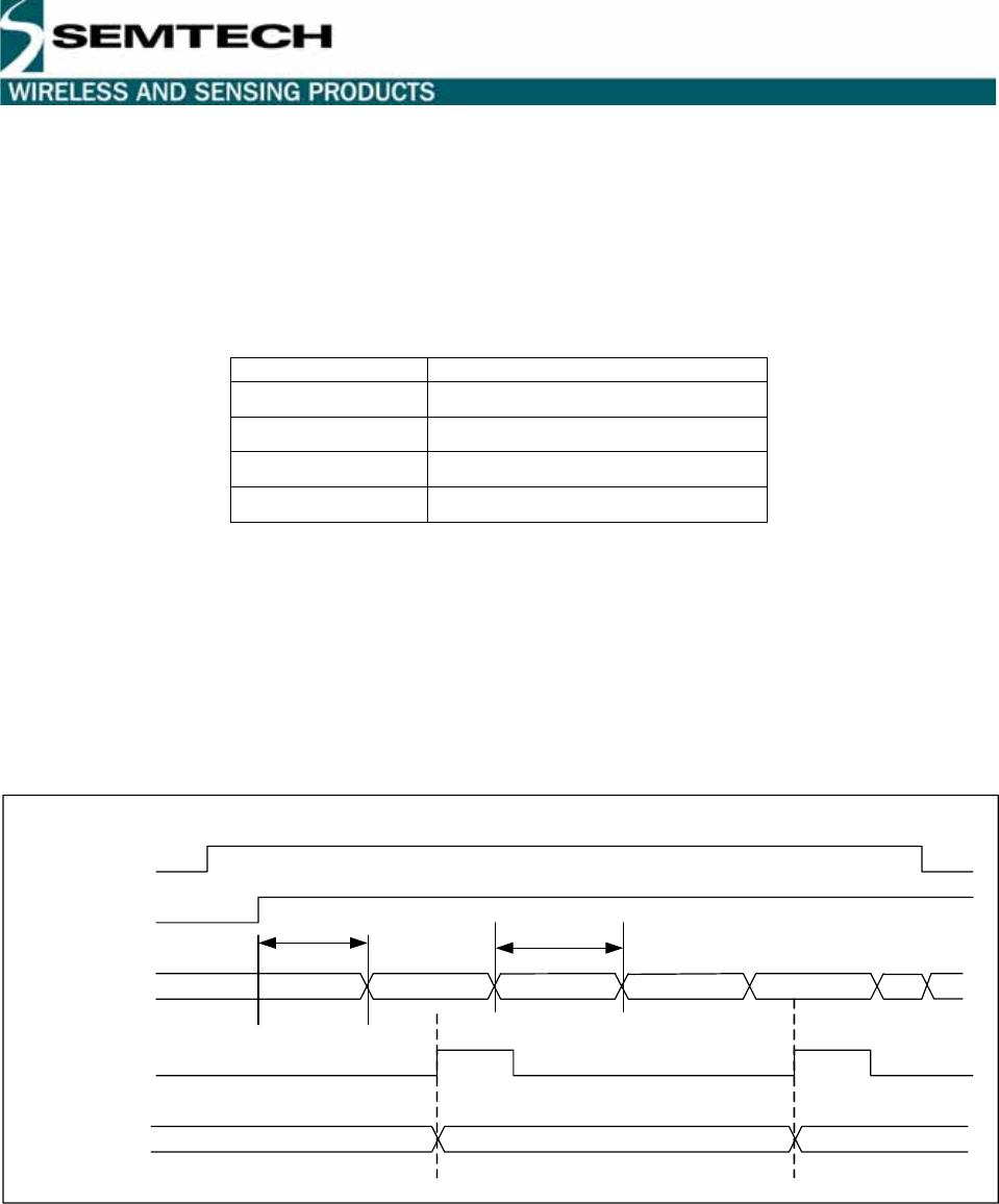
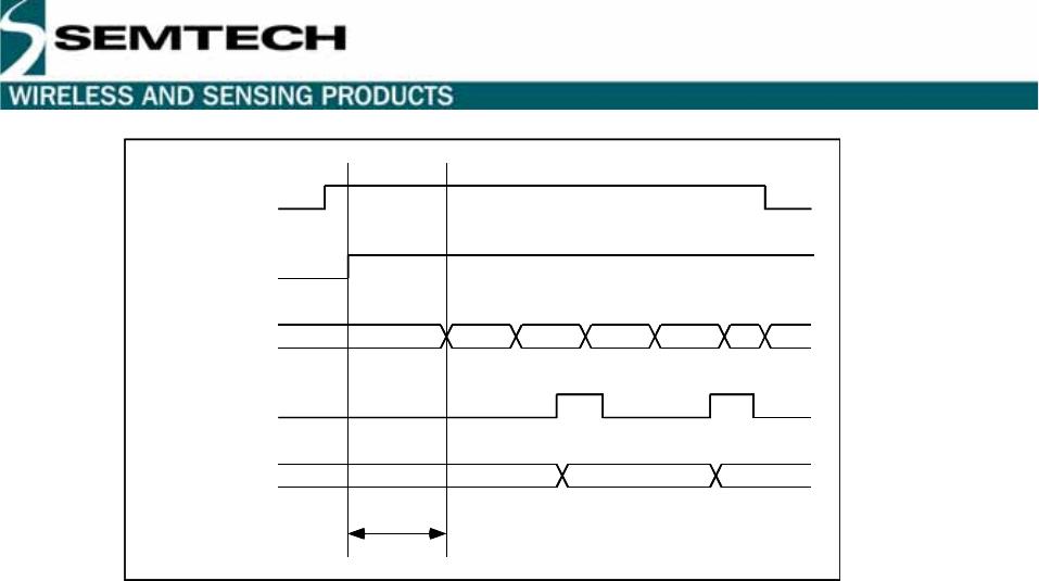
The time diagram of an FEI measurement is similar to that of an RSSI measurement, and is illustrated in Figure 4
below. When the FEI is enabled, the frequency error is periodically measured and the result is stored in the register
“DataOut_FEI” at each rising edge of DATAIN. TS_FE is the wake-up time required after the function has been
enabled to obtain a valid result. For a proper operation, the pulse length on DATAIN has to be higher than 8µs.
© Semtech 2006 www.semtech.com
13
XE1202A TrueRF™
4.1.4.2 “RTParam_Fsel” = 0
With the “RTParam_FEI” bit set to “1” and the RTParam_Fsel” bit set to “0”, the FEI function uses over sampling of
the signal at the output of the demodulator. When activated by the rising edge of DATAIN, this function provides an
8-bit word equivalent to the duty cycle of the demodulated preamble, stored in register “DataOut_FEI”.
Each sample is used to control an up/down counter, when the sample is "1" the content of the counter is
incremented, when the sample is "0" the content of the counter is decremented. As a consequence, the final 8-bit
value of the counter stored in “DataOut_FEI” gives an indication of the duty cycle of the demodulated signal. The
range of stored values is from -128 and +127. The further from 0 the value of DataOut_FEI, the higher the error on
the LO frequency. If the stored value in “DataOut_FEI” is typically zero, then the duty cycle of the preamble is about
50 %, and the LO frequency is nominally correct.
Since this FEI uses the signal before the bit synchronizer, its value can vary from one measurement to another,
due to the presence of jitter and glitches in the signal. If possible, it is advised to make 4-5 measurements and take
the average value.
The timing diagram for this FEI measurement is illustrated in Figure 5 below. The FEI function is activated at the
rising edge of the /EN signal when the RTParam_FEI bit is set to “1”. Then, the internal FEI counter is activated at
the rising edge of DATAIN. After a period TS_FE equal to the duration of 4 bits (see Electrical Specifications), the
counter is stopped and the contents are stored in the register DataOut_FEI. For a proper operation, the pulse
length on DATAIN has to be higher than 8µs.
The maximum delay between the rising edge of DATAIN and the first clock on the internal FEI counter is 1/(16*BR),
where BR is the bit rate.
XX VAL1 VAL2 VAL3 VAL4 XX
XX VAL2 VAL4
RTParam_FEI
fei_out
datain
DataOut_FEI
TS_FE
en
XX VAL1 VAL2 VAL3 VAL4 XX
XX VAL2 VAL4
RTParam_FEI
fei_out
datain
DataOut_FEI
TS_FE
en
Figure 4: FEI measurement timing diagram when “RTParam_Fsel” = 1

XE1202AI027TRLF

Mfr. #:
Manufacturer:
Semtech
Description:
RF Transceiver XE1202AI027TRLF
Lifecycle:
New from this manufacturer.
Delivery:
DHL FedEx Ups TNT EMS
Payment:
T/T Paypal Visa MoneyGram Western Union

Products related to this Datasheet