LTC2921/LTC2922 Series
8
29212fa
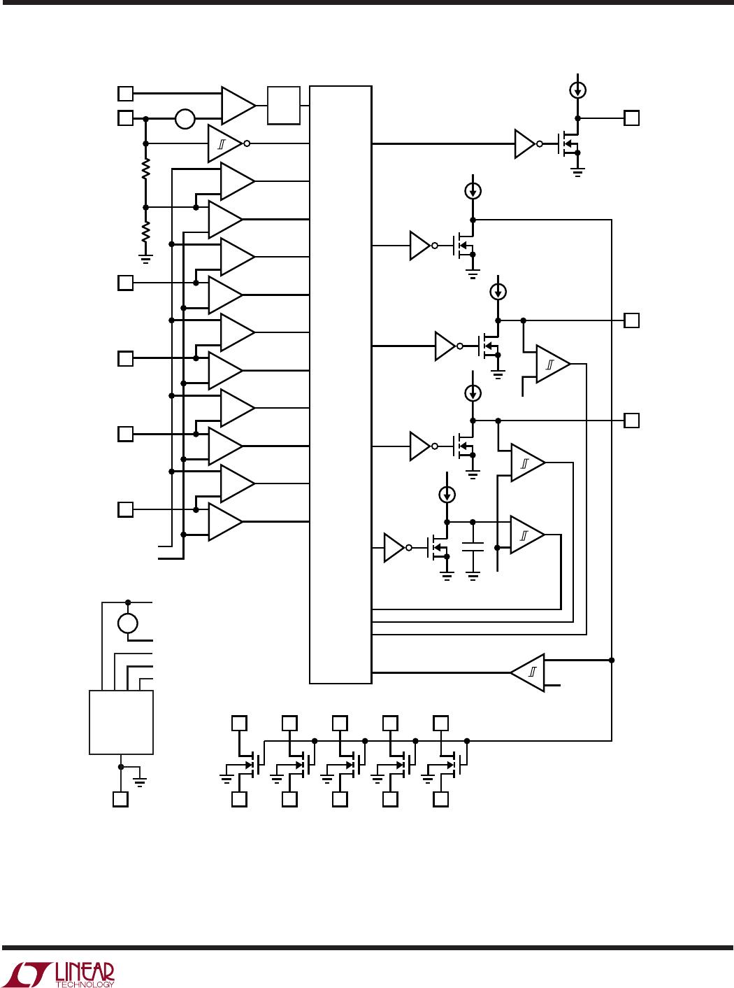
General Operation
The LTC2921 and LTC2922 track multiple supplies, moni-
tor multiple inputs, and provide integrated switches for
remote sensing. Once all input voltages lie between moni-
toring and overvoltage threshold levels, in-line FETs are
turned on to simultaneously ramp power to the loads. The
automatic remote sense switches are then activated, and
the power good signal is asserted. After initial power-on
the LTC2921 and LTC2922 continue monitoring the in-
puts. Several types of events will trigger interruption, any
of which will disconnect all supplies, deactivate the power
good signal, and open the remote sense switches.
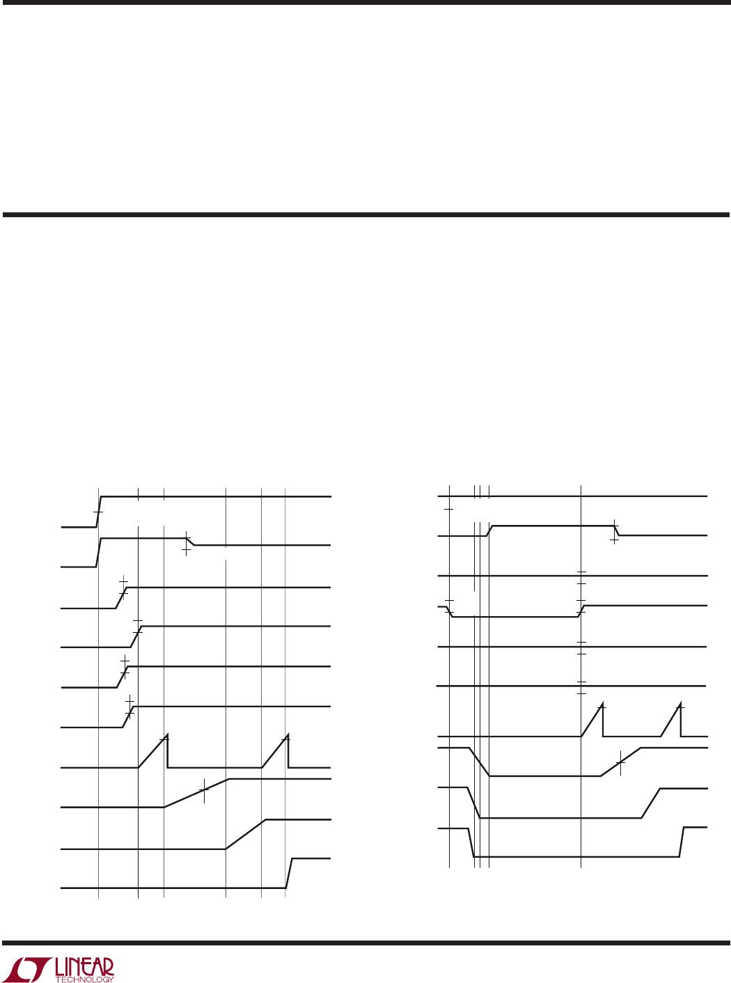
Monitoring Sequence
A normal power-on sequence comprises the following
steps:
Step 0) Wait for V
CC
to exceed the undervoltage lockout
threshold. Continue checking V
CC
.
Step 1) Confirm that the circuit breaker has not tripped and
wait for all monitored supplies, including V
CC
, to be
between their programmed monitor and overvoltage
thresholds. Continue checking these conditions.
Step 2) Check that the TIMER pin voltage starts below
150mV. Create a delay by ramping up the TIMER pin until
it trips an internal comparator.
Step 3) Ramp the GATE pin to turn on the external
N-channel FETs, simultaneously ramping the supplies into
their loads. Await confirmation of full GATE enhancement,
i.e., GATE voltage within ~1V of V
PUMP
. Continue checking
this condition.
Step 4) Activate the remote sense switches. Await confir-
mation of full Feedback Switch Gate enhancement.
Step 5) Wait again for another TIMER cycle delay.
Step 6) Release the pull-down on the PG output. Continue
checking V
CC
, the circuit breaker, the input voltages, and
the GATE voltage.
Interrupting Events
Three events can interrupt the sequence and trigger imme-
diate disconnect of all supplies, pull-down of the PG
signal, and deactivation of the remote sense switches. The
three interrupting events are a lockout, a fault, and an
error.
A lockout occurs when V
CC
falls below the undervoltage
threshold (including hysteresis). Escape from lockout
requires sufficient V
CC
voltage. Leaving lockout, the se-
quence begins at Step 1. A lockout condition supersedes
faults and errors.
A fault occurs when the circuit breaker trips. Escape from
a fault requires pulsing the V1 pin below the reset thresh-
old of 0.5V(nom) for more than 150µs after the current
falls below the trip point. When V1 returns high, the
sequence begins from Step 1. An undervoltage lockout of
>10µs also clears the circuit breaker fault latch. A fault
condition supersedes errors.
An error occurs when one or more of the monitor inputs
(V1-V4 pins) or V
CC
falls below its monitor threshold, or
rises above its overvoltage threshold. A loss of voltage on
the GATE pin, once it has fully ramped up, also causes an
error. An error sends the sequence to Step 1.
Feedback Switches for Remote Sensing
The integrated N-channel switches of the LTC2921/
LTC2922 automatically compensate for the voltage drops
caused by the R
DS(ON)
of the external load-control MOS-
FET switches. This is accomplished by modifying the
normal feedback path of each power supply that is con-
trolled by the LTC2921/LTC2922. When the load-control
switches are off, the remote sense switches are also off,
and the power supply uses its normal feedback path to
sense its output voltage. After the load-control switches
are turned on, the remote sense switches are turned on to
create dominating feedback paths. The feedback loops
include the load-control switches, thus compensating for
their voltage drops.
In order to eliminate glitching on the output of the power
supply, the remote sense switches are turned on at a
controlled rate of about 8V/ms. The gates of these inte-
grated N-channel devices are pulled up above V
CC
to
V
PUMP
so as to provide a low-resistance path for a wide
range of voltages.
OPERATIO
U