AD7400A Data Sheet
Rev. D | Page 2 of 20
TABLE OF CONTENTS
Features .............................................................................................. 1
Applications ....................................................................................... 1
General Description ......................................................................... 1
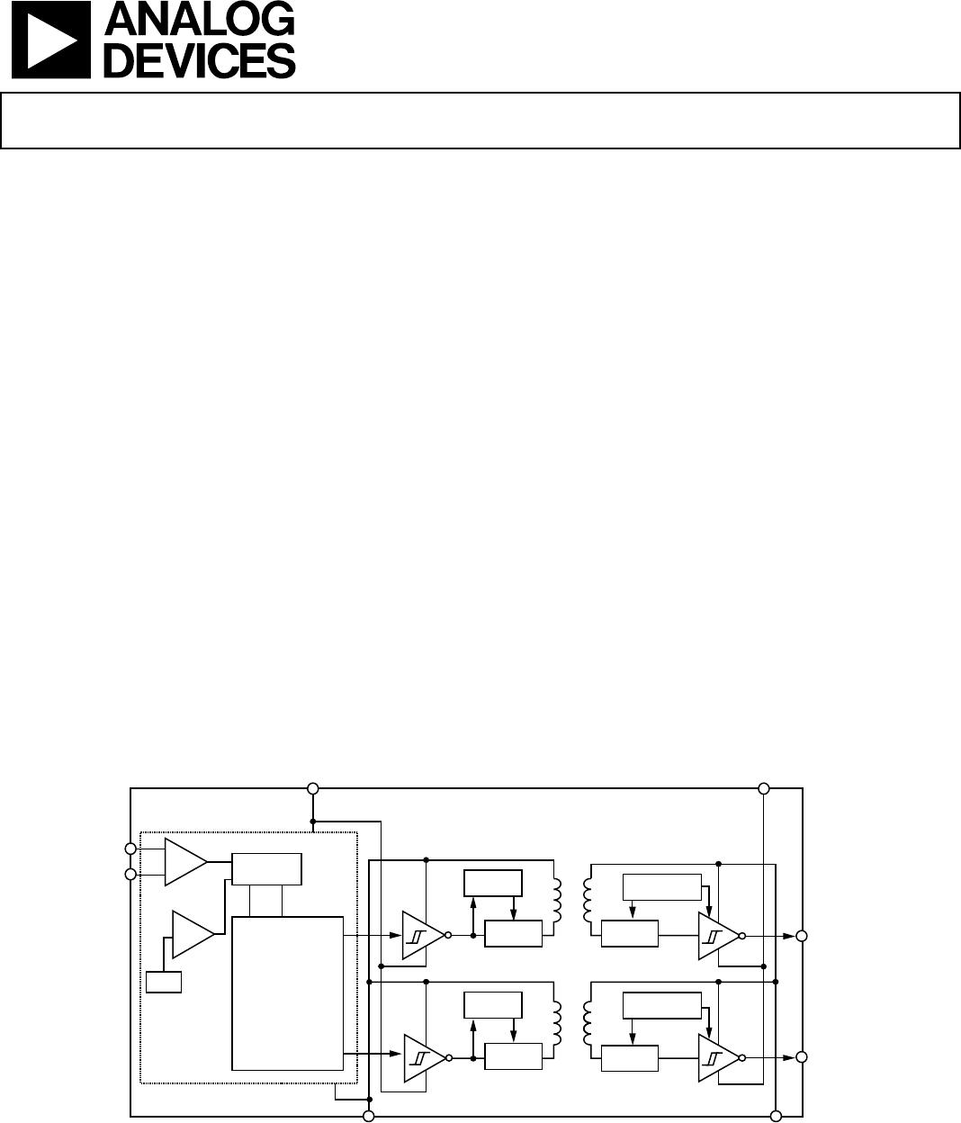
Functional Block Diagram .............................................................. 1
Revision History ............................................................................... 2
Specifications ..................................................................................... 3
Timing Specifications .................................................................. 4
Insulation and Safety-Related Specifications ............................ 5
Regulatory Information ............................................................... 5
DIN V VDE V 0884-10 (VDE V 0884-10) Insulation
Characteristics .............................................................................. 6
Absolute Maximum Ratings ............................................................ 7
ESD Caution .................................................................................. 7
Pin Configuration and Function Descriptions ............................. 8
Typical Performance Characteristics ............................................. 9
Terminology .................................................................................... 12
Theory of Operation ...................................................................... 13
Circuit Information .................................................................... 13
Analog Input ............................................................................... 13
Differential Inputs ...................................................................... 14
Current Sensing Applications ................................................... 14
Voltage Sensing Applications .................................................... 14
Digital Filter ................................................................................ 15
Applications Information .............................................................. 17
Grounding and Layout .............................................................. 17
Evaluating the AD7400A Performance ................................... 17
Insulation Lifetime ..................................................................... 17
Outline Dimensions ....................................................................... 18
Ordering Guide .......................................................................... 18
REVISION HISTORY
11/12—Rev. C to Rev. D
Deleted 8-Lead PDIP ......................................................... Universal
Change to Note 1 .............................................................................. 1
Deleted Figure 5 and Renumbered Sequentially .......................... 8
Updated Outline Dimensions ....................................................... 18
Changes to Ordering Guide .......................................................... 18
7/11—Rev. B to Rev. C
Changes to Minimum External Air Gap (Clearance) Parameter,
Table 3 and Minimum External Tracking (Creepage) Parameter,
Table 3 ................................................................................................ 5
Changes to Figure 6; Pin 1 Description, Table 8; and Pin 7
Description, Table 8 .......................................................................... 8
1/11—Rev. A to Rev. B
Changed UL Recognition from 3750 V rms to 5000 V rms ....... 1
Changes to Input-to-Output Momentary Withstand Voltage
Value (Table 3) .................................................................................. 5
Changed UL Recognition from 3750 V rms to 5000 V rms
(Table 4) .............................................................................................. 5
Changes to Note 1 (Table 4) ............................................................. 5
9/08—Rev. 0 to Rev. A
Added 16-Lead SOIC ......................................................... Universal
Changes to General Description Section ....................................... 1
Changes to Table 1, Test Conditions/Comments Column .......... 3
Changes to Timing Specifications Table Summary ...................... 4
Changes to Table 4, Note 2 ............................................................... 5
Added Figure 6; Renumbered Sequentially ................................... 8
Changes to Terminology Section ................................................. 12
Updated Outline Dimensions ....................................................... 18
Changes to Ordering Guide .......................................................... 18
5/08—Revision 0: Initial Version