10 DS580F6
CS8406
CS8406
+3.3 V or +5.0 V
GND
ILRCK
ISCLK
SDIN
Hardware
Control
APMS
TCBLD
RST
SFMT0
VD VL
TXP
0.1 F
Serial
Audio
Source
Clock Source
and Control
OMCK
SFMT1
TXN
H/S
TCBL
To/from other
CS8406's
CEN
47k
U
Transmission
Interface
User Data
Source
EMPH
AUDIO
ORIG
V
Validity
Source
+3.3 V or +5.0 V
0.1 F
47k
C Data
Source
COPY/C
HWCK1
HWCK0
Figure 6. Recommended Connection Diagram for Hardware Mode
DS580F6 11
CS8406
3. GENERAL DESCRIPTION
The CS8406 is a monolithic CMOS device which encodes a nd transmits audio data according to the AES3,
IEC60958, S/PDIF, and EIAJ CP1201 interface standards. The CS8406 accepts audio, channel status and user da-
ta, which is then multiplexed, encoded, and driven onto a cable.
The audio data is input through a configurable, 3-wire input port. The channel status bits and user bit data are input
through an SPI or I²C Mode microcontroller port and may be assembled in separate block sized buffers.
For systems with no microcontroller, a Stand-Alone Mode allows direct access to channel status and user data input
pins.
Target applications include CD-R, DAT, DVD, MD and VTR equipment, mixing consoles, digital audio transmission
equipment, high quality A/D converters, effects processors, set-top TV boxes, and computer audio systems.
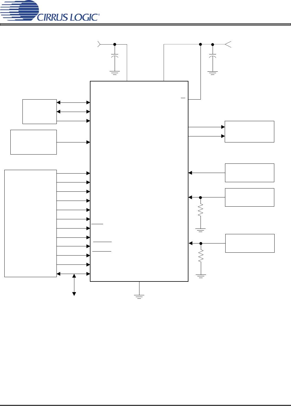
Figure 5 shows the supply and external connections to the CS8406 when configured for operation with a microcon-
troller. Figure 6 shows the supply and external connections to the CS8406 when configured for operation without a
microcontroller.
3.1 AES3 and S/PDIF Standards Documents
This data sheet assumes that the user is familiar with the AES3 and S/PDIF data formats. It is advisable to
have current copies of the AES3 and IEC60958 specifications on hand for easy reference.
The latest AES3 standard is available from the Audio Engi neering Society or ANSI at www.aes.org or
www.ansi.org. Obtain the latest IEC60958 standard from ANSI or from the International Electrotechnical
Commission at www.iec.ch. The latest EIAJ CP-1201 standard is available from the Japanese Electronics
Bureau.
Application Note 22: Overview of Digital Audio Interface Data Structures contains a useful tutorial on digital
audio specifications, but it should not be considered a substitute for the standards.
The paper An Understanding and Implementation of the SCMS Serial Copy Management System for Digital
Audio Transmission, by Clifton Sanchez, is an excellent tutorial on SCMS. It is available from the AES as
reprint 3518.
12 DS580F6
CS8406
4. THREE-WIRE SERIAL INPUT AUDIO PORT
A 3-wire serial audio input port is provided. The interface format can be adjusted to suit the attached device through
the control registers. The following parameters are adjustable:
Master or slave
Serial clock frequency
Audio data resolution
Left or right justification of the data relative to left/right clock
Optional one-bit cell delay of the first data bit
Polarity of the bit clock
Polarity of the left/right clock (by setting the appropriate control bits, many formats are possible.)
Figure 7 shows a selection of common input formats with the corresponding control bit settings.
In Master Mode, the left/right clock and the serial bit clock are outputs, derived from the OMCK input pin master
clock.
In Slave Mode, the left/right clock and the serial bit clock are inputs. The left/right clock must be synchronous to the
OMCK master clock, but the serial bit clock can be asynchronous and discontinuous if required. The left/right clock
should be continuous, but the duty cycle can be less than the specified typical value of 50% if enough serial clocks
are present in each phase to clock all the data bits.
ILRCK
ISCLK
SDIN
2
Left
Justified
(In)
MSB
LSB
Left Right
MSB
I S
(In)
Right
Justified
(In)
MSB LSB MSB LSB MSB
Left
Right
MSB
LSB
MSB LSB
Left
Right
LSB
MSB LSB
ILRCK
ISCLK
SDIN
ILRCK
ISCLK
SDIN
Figure 7. Serial Audio Input Example Formats
X = don’t care to match format, but does need to be set to the desired setting
+ I²S can accept an arbitrary number of bits, determined by the number of ISCLK cycles
* See Serial Input Port Data Format Register Bit Descriptions for an explanation of the meaning of each bit
SIMS* SISF* SIRES[1:0]* SIJUST* SIDEL* SISPOL* SILRPOL*
Left Justified X X 00+ 0 0 0 0
I²S XX00+0101
Right Justified X X XX 1 0 0 0

CS8406-DSZ

Mfr. #:
Manufacturer:
Cirrus Logic
Description:
Audio Transmitters, Receivers, Transceivers 192kHz Digital Audio Transmitter
Lifecycle:
New from this manufacturer.
Delivery:
DHL FedEx Ups TNT EMS
Payment:
T/T Paypal Visa MoneyGram Western Union