DS580F6 19
CS8406
8. CONTROL PORT REGISTER BIT DEFINITIONS
8.1 Memory Address Pointer (MAP)
Not a register
MAP[6:0] - Memory Address Pointer. Will automatically increment after each read or write.
8.2 Default = ‘000000’Control 1 (01h)
VSET - Transmitted Validity bit level
Default = ‘0’
0 - Indicates data is valid, linear PCM audio data
1 - Indicates data is invalid or not linear PCM audio data
MUTEAES - Mute control for the AES transmitter output
Default = ‘0’
0 - Not Muted
1 - Muted
INT1:0 - Interrupt output pin (INT) control
Default = ‘00’
00 - Active high; high output indicates interrupt condition has occurred
01 - Active low, low output indicates an interrupt condition has occurred
10 - Open drain, active low. Requires an external pull-up resistor on the INT pin.
11 - Reserved
TCBLD - Transmit Channel Status Block pin (TCBL) direction specifier
Default = ‘0’
0 - TCBL is an input
1 - TCBL is an output
8.3 Control 2 (02h)
MMT - Select AES3 transmitter mono or stereo operation
Default = ‘0’
0 - Normal stereo operation
1 - Output either left or right channel inputs into consecutive subframe outputs (Mono Mode, left or right is
determined by MMTLR bit)
76543210
0 MAP6 MAP5 MAP4 MAP3 MAP2 MAP1 MAP0
76543210
0 VSET 0 MUTEAES 0 INT1 INT0 TCBLD
76543210
0 0 0 0 0 MMT MMTCS MMTLR
20 DS580F6
CS8406
MMTCS - Select A or B channel status data to transmit in Mono Mode
Default = ‘0’
0 - Use channel A CS data for the A subframe and use channel B CS data for the B subframe
1 - Use the same CS data for both the A and B subframe outputs. If MMTLR = 0, use the left channel CS
data. If MMTLR = 1, use the right channel CS data.
MMTLR - Channel Selection for AES Transmitter Mono Mode
Default = ‘0’
0 - Use left channel input data for consecutive subframe outputs
1- Use right channel input data for consecutive subframe outputs
8.4 Data Flow Control (03h)
The Data Flow Control register configures the flow of audio data. The output data should be muted prior to
changing bits in this register to avoid transients.
TXOFF - AES3 Transmitter Output Driver Control
Default = ‘0
0 - AES3 transmitter output pin drivers normal operation
1 - AES3 transmitter output pin drivers drive to 0 V.
AESBP - AES3 bypass mode selection
Default = ‘0’
0 - Normal operation
1 - Connect the AES3 transmitter driver input di rectly to the RXP pin, which becomes a normal TTL
threshold digital input.
8.5 Clock Source Control (04h)
This register configures the clock sources of various blocks. In conjunction with the Data Flow Control reg-
ister, various Receiver/Transmitter/Transceiver modes may be selected.
RUN - Controls the internal clocks, allowing the CS8406 to be placed in a “powered down” low current con-
sumption, state.
Default = ‘0’
0 - Internal clocks are stopped. Internal state machines are reset. The fully static
control port registers are operational, allowing registers to be read or changed. Reading and
writing the U and C data buffers is not possible. Power consumption is low.
1 - Normal part operation. This bit must be set to 1 to allow the CS8406 to begin operation.
All input clocks should be stable in frequency and phase when RUN is set to 1.
CLK1:0 - Output master clock (OMCK) input frequency to output sample rate (Fs) ratio selector. If these bits
are changed during normal operation, always stop the CS8406 first (RUN = 0), write the new value, then
start the CS8406 (RUN = 1).
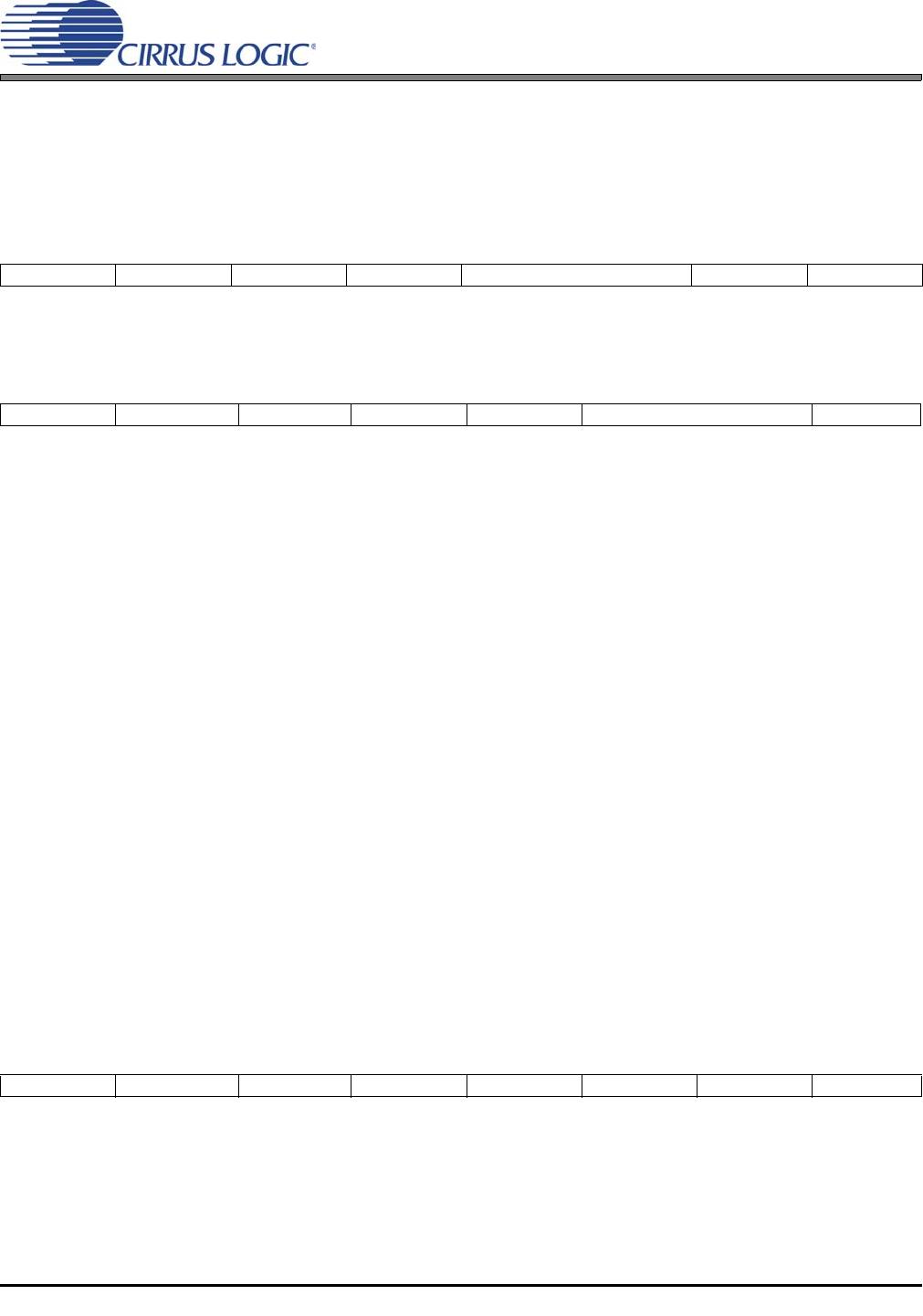
7 6 543210
0 TXOFF AESBP 0 0 0 0 0
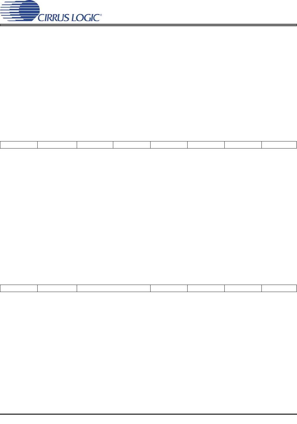
7 6 543210
0 RUN CLK1 CLK0 0 0 0 0
DS580F6 21
CS8406
Default = ‘00’
00 - OMCK frequency is 256*Fs
01 - OMCK frequency is 384*Fs
10 - OMCK frequency is 512*Fs
11 - OMCK frequency is 128*Fs
8.6 Serial Audio Input Port Data Format (05h)
SIMS - Master/Slave Mode Selector
Default = ‘0’
0 - Serial audio input port is in Slave Mode
1 - Serial audio input port is in Master Mode
SISF - ISCLK frequency (for Master Mode)
Default = ‘0’
0 - 64*Fs
1 - 128*Fs
SIRES1:0 - Resolution of the input data, for right-justified formats
Default = ‘00’
00 - 24-bit resolution
01 - 20-bit resolution
10 - 16-bit resolution
11 - Reserved
SIJUST - Justification of SDIN data relative to ILRCK
Default = ‘0’
0 - Left-justified
1 - Right-justified
SIDEL - Delay of SDIN data relative to ILRCK, for left-justified data formats
Default = ‘0’
0 - MSB of SDIN data occurs in the first ISCLK period after the ILRCK edge (Left-Justified Mode)
1 - MSB of SDIN data occurs in the second ISCLK period after the ILRCK edge (I²S Mode)
SISPOL - ISCLK clock polarity
Default = ‘0’
0 - SDIN sampled on rising edges of ISCLK
1 - SDIN sampled on falling edges of ISCLK
SILRPOL - ILRCK clock polarity
Default = ‘0’
0 - SDIN data is for the left channel when ILRCK is high
1 - SDIN data is for the right channel when ILRCK is high
76543210
SIMS SISF SIRES1 SIRES0 SIJUST SIDEL SISPOL SILRPOL

CS8406-DSZ

Mfr. #:
Manufacturer:
Cirrus Logic
Description:
Audio Transmitters, Receivers, Transceivers 192kHz Digital Audio Transmitter
Lifecycle:
New from this manufacturer.
Delivery:
DHL FedEx Ups TNT EMS
Payment:
T/T Paypal Visa MoneyGram Western Union