LT6109-1/LT6109-2
1
610912fa
TYPICAL APPLICATION
FEATURES DESCRIPTION
High Side Current Sense
Amplifier with Reference
and Comparators
The LT
®
6109 is a complete high side current sense device
that incorporates a precision current sense amplifier, an
integrated voltage reference and two comparators. Two
versions of the LT6109 are available. The LT6109-1 has
the comparators connected in opposing polarity and the
LT6109-2 has the comparators connected in the same polar-
ity. In addition, the current sense amplifier and comparator
inputs and outputs are directly accessible. The amplifier
gain and comparator trip points are configured by external
resistors. The open-drain comparator outputs allows for
easy interface to other system components.
The overall propagation delay of the LT6109 is typically
only 1.4µs, allowing for quick reaction to overcurrent
and undercurrent conditions. The 1MHz bandwidth al-
lows the LT6109 to be used for error detection in critical
applications such as motor control. The high threshold
accuracy of the comparators, combined with the ability to
latch both comparators, ensures the LT6109 can capture
high speed events.
The LT6109 is fully specified for operation from –40°C to
125°C, making it suitable for industrial and automotive ap-
plications. The LT6109 is available in a small 10-lead MSOP.
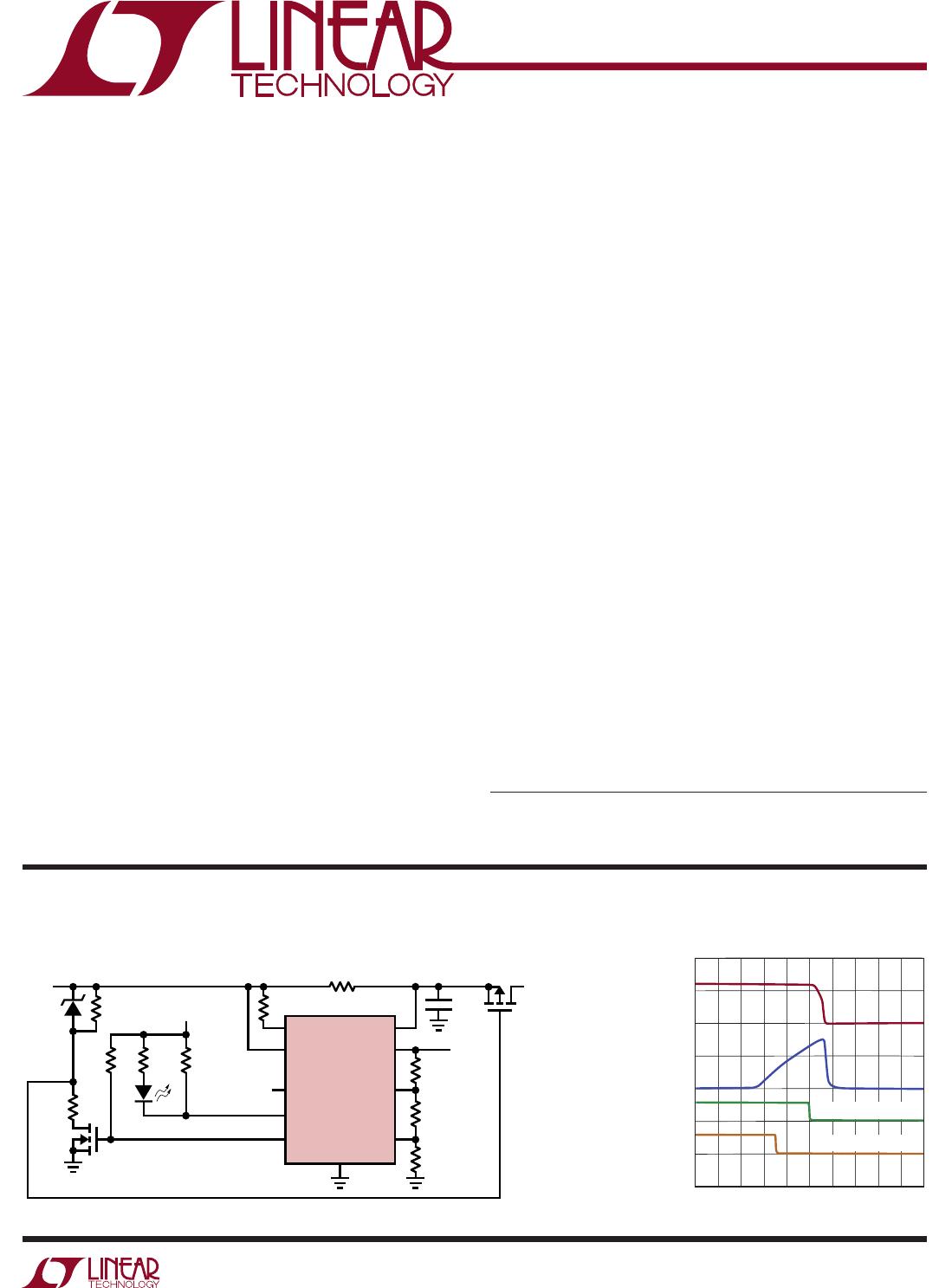
Circuit Fault Protection with Latching Load Disconnect and Early Warning Indication
APPLICATIONS
n
Current Sense Amplifier
Fast Step Response: 500ns
Low Offset Voltage: 125µV Maximum
Low Gain Error: 0.2% Maximum
n
Internal 400mV Precision Reference
n
Internal Latching Comparators with Reset
Fast Response Time: 500ns
Total Threshold Error: ±1.25% Maximum
Two Comparator Polarity Options
n
Wide Supply Range: 2.7V to 60V
n
Supply Current: 550µA
n
Low Shutdown Current: 5µA Maximum
n
Specified for –40°C to 125°C Temperature Range
n
Available in 10-Lead MSOP Package
n
Overcurrent, Undercurrent and Fault Detection
n
Current Shunt Measurement
n
Battery Monitoring
n
Motor Control
n
Automotive Monitoring and Control
n
Remote Sensing
n
Industrial Control
L, LT, LTC, LTM, TimerBlox, Linear Technology and the Linear logo are registered trademarks
of Linear Technology Corporation. All other trademarks are the property of their respective
owners.
Response to Overcurrent Event
SENSEHI SENSELO
OUTA
LT6109-2
INC2RESET
INC12N2700
100mA WARNING
250mA DISCONNECT
*CMH25234B
V
+
EN/RST
OUTC1
OUTC2
V
0.1Ω
IRF9640
3.3V
6.2V*
12V
100Ω
6.04k
100k
1.62k10k
1k
1k
0.1µF
V
OUT
2.37k
1.6k
610912 TA01a
TO LOAD
5µs/DIV
V
LOAD
10V/DIV
V
OUTC1
5V/DIV
I
LOAD
200mA/DIV
0V
0V
V
OUTC2
5V/DIV
0V
0mA
610912 TA01b
250mA DISCONNECT
100mA WARNING
LT6109-1/LT6109-2
2
610912fa
PIN CONFIGURATIONABSOLUTE MAXIMUM RATINGS
Total Supply Voltage (V
+
to V
) .................................60V
Maximum Voltage
(SENSELO, SENSEHI, OUTA)
............................... V
+
+ 1V
Maximum V
+
– (SENSELO or SENSEHI) ....................33V
Maximum EN/RST Voltage
........................................ 60V
Maximum Comparator Input Voltage
........................60V
Maximum Comparator Output Voltage......................60V
Input Current (Note 2)
..........................................–10mA
SENSEHI, SENSELO Input Current
....................... ±10mA
Differential SENSEHI or SENSELO Input Current
...±2.5mA
Amplifier Output Short-Circuit Duration (to V
) .. Indefinite
Operating Temperature Range (Note 3)
LT6109I ................................................40°C to 85°C
LT6109H ............................................ 40°C to 125°C
Specified Temperature Range (Note 3)
LT6109I ................................................40°C to 85°C
LT6109H ............................................ 40°C to 125°C
Maximum Junction Temperature
.......................... 150°C
Storage Temperature Range
.................. 65°C to 150°C
Lead Temperature (Soldering, 10 sec)
...................300°C
(Note 1)
1
2
3
4
5
SENSELO
EN/RST
OUTC2
OUTC1
V
10
9
8
7
6
SENSEHI
V
+
OUTA
INC2
INC1
TOP VIEW
MS PACKAGE
10-LEAD PLASTIC MSOP
θ
JA
= 160°C/W, θ
JC
= 45°C/W
ORDER INFORMATION
LEAD FREE FINISH TAPE AND REEL PART MARKING* PACKAGE DESCRIPTION SPECIFIED TEMPERATURE RANGE
LT6109AIMS-1#PBF LT6109AIMS-1#TRPBF LTFNJ 10-Lead Plastic MSOP –40°C to 85°C
LT6109IMS-1#PBF LT6109IMS-1#TRPBF LTFNJ 10-Lead Plastic MSOP –40°C to 85°C
LT6109AHMS-1#PBF LT6109AHMS-1#TRPBF LTFNJ 10-Lead Plastic MSOP –40°C to 125°C
LT6109HMS-1#PBF LT6109HMS-1#TRPBF LTFNJ 10-Lead Plastic MSOP –40°C to 125°C
LT6109AIMS-2#PBF LT6109AIMS-2#TRPBF LT FWY 10-Lead Plastic MSOP –40°C to 85°C
LT6109IMS-2#PBF LT6109IMS-2#TRPBF LT FWY 10-Lead Plastic MSOP –40°C to 85°C
LT6109AHMS-2#PBF LT6109AHMS-2#TRPBF LT FWY 10-Lead Plastic MSOP –40°C to 125°C
LT6109HMS-2#PBF LT6109HMS-2#TRPBF LT FWY 10-Lead Plastic MSOP –40°C to 125°C
Consult LTC Marketing for parts specified with wider operating temperature ranges. *The temperature grade is identified by a label on the shipping container.
Consult LTC Marketing for information on non-standard lead based finish parts.
For more information on lead free part marking, go to: http://www.linear.com/leadfree/
For more information on tape and reel specifications, go to: http://www.linear.com/tapeandreel/
LT6109-1/LT6109-2
3
610912fa
ELECTRICAL CHARACTERISTICS
The l denotes the specifications which apply over the full operating
temperature range, otherwise specifications are at T
A
= 25°C. V
+
= 12V, V
PULLUP
= V
+
, V
EN/RST
= 2.7V, R
IN
= 100Ω,
R
OUT
= R1 + R2 + R3 = 10k, gain = 100, R
C
= 25.5k, C
L
= C
LC
= 2pF, unless otherwise noted. (See Figure 3)
SYMBOL PARAMETER CONDITIONS MIN TYP MAX UNITS
V
+
Supply Voltage Range
l
2.7 60 V
I
S
Supply Current (Note 4) V
+
= 2.7V, R
IN
= 1k, V
SENSE
= 5mV 475 µA
V
+
= 60V, R
IN
= 1k, V
SENSE
= 5mV
l
600 700
1000
µA
µA
Supply Current in Shutdown V
+
= 2.7V, V
EN/RST
= 0V, R
IN
= 1k, V
SENSE
= 0.5V
l
3 5
7
µA
µA
V
+
= 60V, V
EN/RST
= 0V, R
IN
= 1k, V
SENSE
= 0.5V
l
7 11
13
µA
µA
EN/RST Pin Current V
EN/RST
= 0V, V
+
= 60V –200 nA
V
IH
EN/RST Pin Input High V
+
= 2.7V to 60V
l
1.9 V
V
IL
EN/RST Pin Input Low V
+
= 2.7V to 60V
l
0.8 V
Current Sense Amplifier
V
OS
Input Offset Voltage V
SENSE
= 5mV, LT6109A
V
SENSE
= 5mV, LT6109
V
SENSE
= 5mV, LT6109A
V
SENSE
= 5mV, LT6109
l
l
–125
–350
–250
–450
125
350
250
450
µV
µV
µV
µV
V
OS
/T
Input Offset Voltage Drift V
SENSE
= 5mV
l
±0.8 µV/°C
I
B
Input Bias Current
(SENSELO, SENSEHI)
V
+
= 2.7V to 60V
l
60 300
350
nA
nA
I
OS
Input Offset Current V
+
= 2.7V to 60V ±5 nA
I
OUTA
Output Current (Note 5)
l
1 mA
PSRR Power Supply Rejection Ratio
(Note 6)
V
+
= 2.7V to 60V
l
120
114
127 dB
dB
CMRR Common Mode Rejection Ratio V
+
= 36V, V
SENSE
= 5mV, V
ICM
= 2.7V to 36V 125 dB
V
+
= 60V, V
SENSE
= 5mV, V
ICM
= 27V to 60V
l
110
103
125 dB
dB
V
SENSE(MAX)
Full-Scale Input Sense Voltage
(Note 5)
R
IN
= 500Ω
l
500 mV
Gain Error (Note 7) V
+
= 2.7V to 12V
V
+
= 12V to 60V, V
SENSE
= 5mV to 100mV
l
–0.2
–0.08
0
%
%
SENSELO Voltage (Note 8) V
+
= 2.7V, V
SENSE
= 100mV, R
OUT
= 2k
V
+
= 60V, V
SENSE
= 100mV
l
l
2.5
27
V
V
Output Swing High (V
+
to V
OUTA
) V
+
= 2.7V, V
SENSE
= 27mV
l
0.2 V
V
+
= 12V, V
SENSE
= 120mV
l
0.5 V
BW Signal Bandwidth I
OUT
= 1mA
I
OUT
= 100µA
1
140
MHz
kHz
t
r
Input Step Response (to 50% of
Final Output Voltage)
V
+
= 2.7V, V
SENSE
= 24mV Step, Output Rising Edge
V
+
= 12V to 60V, V
SENSE
= 100mV Step, Output Rising Edge
500
500
ns
ns
t
SETTLE
Settling Time to 1% V
SENSE
= 10mV to 100mV, R
OUT
= 2k 2 µs

LT6109AIMS-2#PBF

Mfr. #:
Manufacturer:
Analog Devices Inc.
Description:
Current Sense Amplifiers Current Sense Amp with Reference and Comparators
Lifecycle:
New from this manufacturer.
Delivery:
DHL FedEx Ups TNT EMS
Payment:
T/T Paypal Visa MoneyGram Western Union