LT6109-1/LT6109-2
4
610912fa
ELECTRICAL CHARACTERISTICS
The l denotes the specifications which apply over the full operating
temperature range, otherwise specifications are at T
A
= 25°C. V
+
= 12V, V
PULLUP
= V
+
, V
EN/RST
= 2.7V, R
IN
= 100Ω,
R
OUT
= R1 + R2 + R3 = 10k, gain = 100, R
C
= 25.5k, C
L
= C
LC
= 2pF, unless otherwise noted. (See Figure 3)
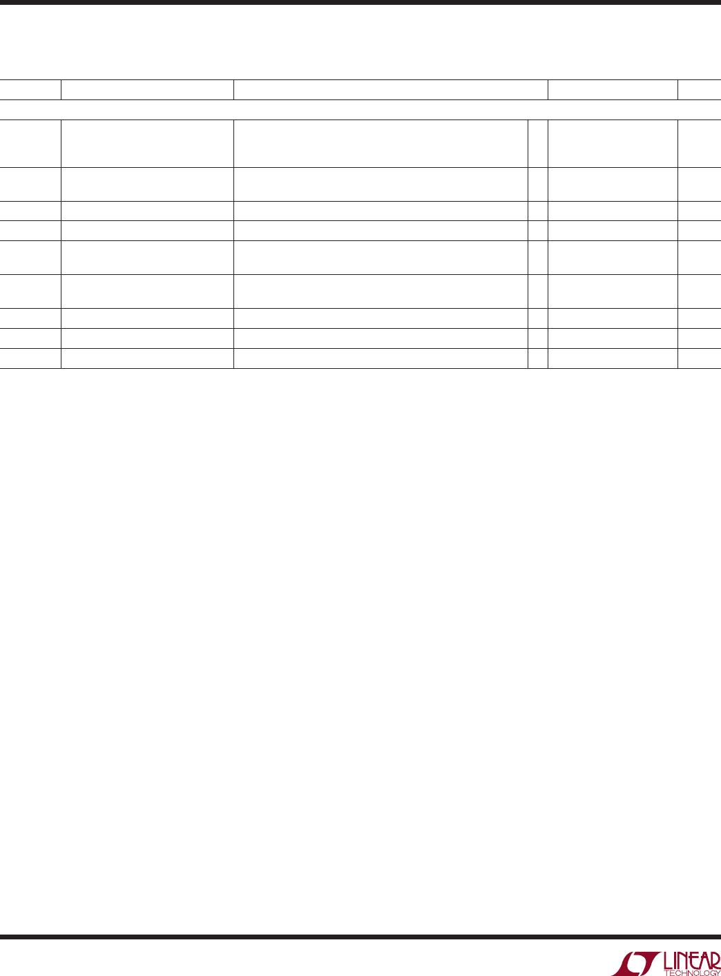
SYMBOL PARAMETER CONDITIONS MIN TYP MAX UNITS
Reference and Comparator
V
TH(R)
(Note 9)
Rising Input Threshold Voltage
(LT6109-1 Comparator 1
LT6109-2 Both Comparators)
V
+
= 2.7V to 60V, LT6109A
V
+
= 2.7V to 60V, LT6109
l
l
395
392
400
400
405
408
mV
mV
V
TH(F)
(Note 9)
Falling Input Threshold Voltage
(LT6109-1 Comparator 2)
V
+
= 2.7V to 60V, LT6109A
V
+
= 2.7V to 60V, LT6109
l
l
395
392
400
400
405
408
mV
mV
V
HYS
V
HYS
= V
TH(R)
– V
TH(F)
V
+
= 2.7V to 60V 3 10 15 mV
Comparator Input Bias Current V
INC1,2
= 0V, V
+
= 60V
l
–50 nA
V
OL
Output Low Voltage I
OUTC1,C2
= 500µA, V
+
= 2.7V
l
60 150
220
mV
mV
High to Low Propagation Delay 5mV Overdrive
100mV Overdrive
3
0.5
µs
µs
Output Fall Time 0.08 µs
t
RESET
Reset Time 0.5 µs
t
RPW
Valid RST Pulse Width
l
2 15 µs
Note 1: Stresses beyond those listed under Absolute Maximum Ratings
may cause permanent damage to the device. Exposure to any Absolute
Maximum Rating condition for extended periods may affect device
reliability and lifetime.
Note 2: Input and output pins have ESD diodes connected to ground. The
SENSEHI and SENSELO pins have additional current handling capability
specified as SENSEHI, SENSELO input current.
Note 3: The LT6109I is guaranteed to meet specified performance from
–40°C to 85°C. LT6109H is guaranteed to meet specified performance
from –40°C to 125°C.
Note 4: Supply current is specified with the comparator outputs high.
When the comparator outputs go low the supply current will increase by
75µA typically per comparator.
Note 5: The full-scale input sense voltage and the maximum output
current must be considered to achieve the specified performance.
Note 6: Supply voltage and input common mode voltage are varied while
amplifier input offset voltage is monitored.
Note 7: Specified gain error does not include the effects of external
resistors R
IN
and R
OUT
. Although gain error is only guaranteed between
12V and 60V, similar performance is expected for V
+
< 12V, as well.
Note 8: Refer to SENSELO, SENSEHI Range in the Applications
Information section for more information.
Note 9: The input threshold voltage which causes the output voltage of the
comparator to transition from high to low is specified. The input voltage
which causes the comparator output to transition from low to high is
the magnitude of the difference between the specified threshold and the
hysteresis.
LT6109-1/LT6109-2
5
610912fa
TYPICAL PERFORMANCE CHARACTERISTICS
Input Offset Voltage
vs Temperature
Amplifier Offset Voltage
vs Supply Voltage Offset Voltage Drift Distribution
Amplifier Gain Error
vs Temperature
Amplifier Gain Error Distribution
Supply Current vs Supply Voltage Start-Up Supply Current Enable/Disable Response
Performance characteristics taken at T
A
= 25°C,
V
+
= 12V, V
PULLUP
= V
+
, V
EN/RST
= 2.7V, R
IN
= 100Ω, R
OUT
= R1 + R2 + R3 = 10k, gain = 100, R
C
= 25.5k, C
L
= C
LC
= 2pF, unless
otherwise noted. (See Figure 3)
SUPPLY VOLTAGE (V)
0
700
600
500
400
300
200
100
0
30 50
610912 G01
10 20
40 60
SUPPLY CURRENT (µA)
SUPPLY VOLTAGE (V)
0
–100
OFFSET VOLTAGE (µV)
–60
–20
20
10
20
30 40
610912 G05
50
60
100
–80
–40
0
40
80
60
5 TYPICAL UNITS
0V
V
+
5V/DIV
I
S
500µA/DIV
0µA
10µs/DIV
610912 G02
100µs/DIV
V
EN/RST
2V/DIV
I
S
500µA/DIV
0V
0µA
610912 G03
TEMPERATURE (°C)
–40
INPUT OFFSET VOLTAGE (µV)
300
200
100
0
–100
–200
–300
80
610912 G04
–10 20 50 12511065–25 5 35 95
5 TYPICAL UNITS
OFFSET VOLTAGE DRIFT (µV/°C)
6
8
12
610912 G06
4
2
0–0.5 0.5–1 1 1.5 2–1.5–2
0
10
PERCENTAGE OF UNITS (%)
TEMPERATURE (°C)
–50 –25
–0.20
GAIN ERROR (%)
–0.10
0.05
0
50
75
610912 G07
–0.15
0
–0.05
25
100
125
R
IN
= 1k
R
IN
= 100Ω
V
SENSE
= 5mV TO 100mV
GAIN ERROR (%)
–0.048
0
PERCENTAGE OF UNITS (%)
5
15
20
25
V
SENSE
= 5mV TO 100mV
–0.052
–0.056
610912 G08
10
–0.060
–0.68
–0.064
Amplifier Output Swing
vs Temperature
TEMPERATURE (°C)
–50
0
V
+
– V
OUTA
(V)
0.05
0.15
0.20
0.25
0.50
0.35
0
50
75
610912 G18
0.10
0.40
0.45
0.30
–25
25
100
125
V
+
= 12V
V
SENSE
= 120mV
V
+
= 2.7V
V
SENSE
= 27mV
LT6109-1/LT6109-2
6
610912fa
Performance characteristics taken at T
A
= 25°C,
V
+
= 12V, V
PULLUP
= V
+
, V
EN/RST
= 2.7V, R
IN
= 100Ω, R
OUT
= R1 + R2 + R3 = 10k, gain = 100, R
C
= 25.5k, C
L
= C
LC
= 2pF, unless
otherwise noted. (See Figure 3)
Amplifier Input Bias Current
vs Temperature
Amplifier Step Response
(V
SENSE
= 0mV to 100mV)
Amplifier Step Response
(V
SENSE
= 0mV to 100mV)
Amplifier Step Response
(V
SENSE
= 10mV to 100mV)
Amplifier Step Response
(V
SENSE
= 10mV to 100mV)
Amplifier Gain vs Frequency
System Step Response
Common Mode Rejection Ratio
vs Frequency
TYPICAL PERFORMANCE CHARACTERISTICS
FREQUENCY (Hz)
1
0
COMMON MODE REJECTION RATIO (dB)
120
100
10 100 1k 10k 100k 1M 10M
610912 G10
80
60
40
20
FREQUENCY (Hz)
22
GAIN (dB)
28
34
40
46
1k 100k 1M 10M
610912 G11
16
10k
I
OUTA
= 1mA
I
OUTA
= 100µA
G = 100
G = 50, R
OUT
= 5k
G = 20, R
OUT
= 2k
0V
V
SENSE
100mV/DIV
V
OUTA
1V/DIV
V
OUTC1
2V/DIV
V
EN/RST
5V/DIV
0V
0V
0V
610912 G12
2µs/DIV
R
OUT
= 2k,100mV INC1 OVERDRIVE
TEMPERATURE (°C)
–25
INPUT BIAS CURRENT (nA)
60
80
100
95
610912 G13
40
20
50
70
90
30
10
0
5
35
65
–10–40 110
20
50
80
125
SENSEHI
SENSELO
V
OUTA
2V/DIV
V
SENSE
50mV/DIV
0V
0V
610912 G14
2µs/DIV
R
IN
= 100Ω
G = 100V/V
V
OUTA
2V/DIV
V
SENSE
50mV/DIV
0V
0V
610912 G15
2µs/DIV
R
IN
= 100Ω
G = 100V/V
0V
0V
V
OUTA
1V/DIV
V
SENSE
100mV/DIV
610912 G16
2µs/DIV
R
IN
= 1k
R
OUT
= 20k
G = 20V/V
0V
0V
V
OUTA
1V/DIV
V
SENSE
100mV/DIV
610912 G17
2µs/DIV
R
IN
= 1k
R
OUT
= 20k
G = 20V/V
Power Supply Rejection Ratio
vs Frequency
FREQUENCY (Hz)
1
0
120
100
140
160
10 100 1k 10k 100k 1M 10M
610912 G09
80
60
40
20

LT6109AIMS-2#PBF

Mfr. #:
Manufacturer:
Analog Devices Inc.
Description:
Current Sense Amplifiers Current Sense Amp with Reference and Comparators
Lifecycle:
New from this manufacturer.
Delivery:
DHL FedEx Ups TNT EMS
Payment:
T/T Paypal Visa MoneyGram Western Union