6.42
IDT7133SA/LA, IDT7143SA/LA
High-Speed 2K x 16 Dual-Port RAM Military, Industrial and Commercial Temperature Ranges
4
Capacitance (TA = +25°C, f = 1.0mhz)
Recommended DC Operating
Conditions
Maximum Operating
Temperature and Supply Voltage
(1,2)
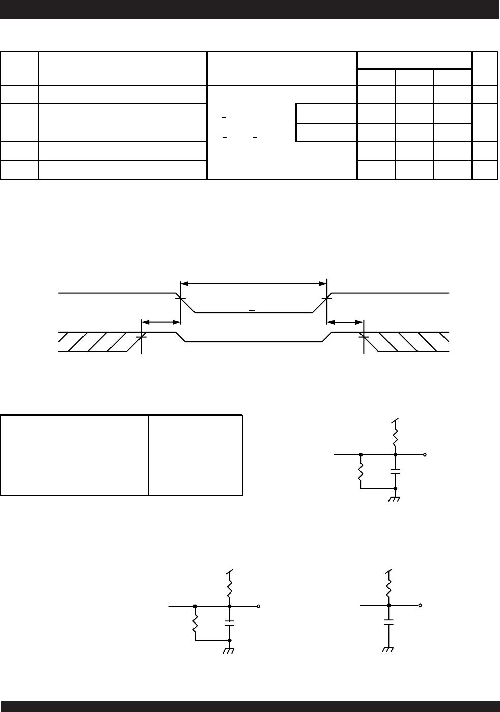
Absolute Maximum Ratings
(1)
DC Electrical Characteristics Over the Operating
Temperature and Supply Voltage Range
(Either port, VCC = 5.0V ± 10%)
NOTE:
1. At Vcc
< 2.0V, input leakages are undefined.
NOTES:
1. Stresses greater than those listed under ABSOLUTE MAXIMUM RATINGS may
cause permanent damage to the device. This is a stress rating only and functional
operation of the device at these or any other conditions above those indicated in
the operational sections of this specification is not implied. Exposure to absolute
maximum rating conditions for extended periods may affect reliability.
2. V
TERM must not exceed Vcc + 10% for more than 25% of the cycle time or 10ns
maximum, and is limited to
< 20mA for the period of VTERM > Vcc + 10%.
NOTES:
1. This parameter is determined by device characterization but is not production
tested.
2. 3dV references the interpolated capacitance when the input and output switch from
0V to 3V or from 3V to 0V.
NOTES:
1. This is the parameter T
A. This is the "instant on" case temperature.
NOTES:
1. V
IL (min.) = -1.5V for pulse width less than 10ns.
2. V
TERM must not exceed Vcc + 10%.
Grade Ambient
Temperature
GND Vcc
Military -55
O
C to +125
O
C0V 5.0V
+
10%
Commercial 0
O
C to +70
O
C0V 5.0V
+
10%
Industrial -40
O
C to +85
O
C0V 5.0V
+
10%
2746 tbl 04
Symbol Parameter
(1 )
Conditions
(2 )
Max. Unit
C
IN
Input Capacitance V
IN
= 3dV 11 pF
C
OUT
Output Capacitance V
OUT
= 3dV 11 pF
2746 tbl 03
Symbol Parameter Min. Typ. Max. Unit
V
CC
Supply Voltage 4.5 5.0 5.5 V
GND Ground 0 0 0 V
V
IH
Input High Voltage 2.2
____
6.0
(2 )
V
V
IL
Input Low Voltage -0.5
(1)
____
0.8 V
2746 tbl 05
Symbol Parameter Test Conditions
7133SA
7143SA
7133LA
7143LA
UnitMin. Max. Min. Max.
|I
LI
| Input Leakage Current
(1)
V
CC
= 5.5V, V
IN
= 0V to V
CC
___
10
___
A
|I
LO
| Output Leakage Current
CE = V
IH
, V
OUT
= 0V to V
CC
___
10
___
A
V
OL
Output Low Voltage (I/O
0
-I/O
15
)I
OL
= 4mA
___
0.4
___
0.4 V
V
OL
Open Drain Output Low Voltage
(BUSY)
I
OL
= 16mA
___
0.5
___
0.5 V
V
OH
Output High Voltage I
OH
= -4mA 2.4
___
2.4
___
V
2746 tbl 06
Symbol Rating Commercial
& Industrial
Military Unit
V
TERM
(2)
Terminal Voltage
with Respect
to GND
-0.5 to +7.0 -0.5 to +7.0 V
T
BIAS
Temperature
Under Bias
-55 to +125 -65 to +135
o
C
T
STG
Storage
Temperature
-65 to +150 -65 to +150
o
C
P
T
Power
Dissipation
2.0 2.0 W
I
OUT
DC Output
Current
50 50 mA
2746 tbl 02
6.42
IDT7133SA/LA, IDT7143SA/LA
High-Speed 2K x 16 Dual-Port RAM Military, Industrial and Commercial Temperature Ranges
5
NOTES:
1. V
CC = 5V, TA = +25°C for Typ., and are not production tested. ICCDC = 180mA (typ.)
2. 'X' in part number indicates power rating (SA or LA)
3. At f = f
MAX, address and control lines (except Output Enable) are cycling at the maximum frequency read cycle of 1/ tRC, and using “AC Test Conditions" of input levels of
GND to 3V.
4. f = 0 means no address or control lines change. Applies only to inputs at CMOS level standby.
5. Port "A" may be either left or right port. Port "B" is the opposite from port "A".
DC Electrical Characteristics Operating
Temperature and Supply Voltage Range
(2)
(VCC = 5.0V ± 10%)
7133X20
7143X20
Com'l Only
7133X25
7143X25
Com'l & Ind
7133X35
7143X35
Com'l
& Military
Symbol Parameter Test Condition Version Typ.
(1)
Max. Typ.
(1)
Max. Typ.
(1)
Max. Unit
I
CC
Dynamic Operating
Current
(Both Ports Active)
CE = V
IL
, Outputs Disabled
f = f
MAX
(3)
COM'L S
L
250
230
310
280
250
230
300
270
240
210
295
250
mA
MIL &
IND
S
L
____
____
____
____
250
230
330
300
240
220
325
295
I
SB1
Standby Current
(Both Ports - TTL
Leve l Inputs)
CE
L
and CE
R
= V
IH
f = f
MAX
(3)
COM'L S
L
25
25
80
70
25
25
80
70
25
25
70
60
mA
MIL &
IND
S
L
____
____
____
____
25
25
90
80
25
25
75
65
I
SB2
Standby Current
(One Port - TTL
Leve l Inputs)
CE
"A"
= V
IL
and CE
"B"
= V
IH
(4)
f=f
MAX
(3)
Active Port Outputs Disabled
COM'L S
L
140
120
200
180
140
100
200
170
120
100
180
160
mA
MIL &
IND
S
L
____
____
____
____
140
100
230
190
120
100
200
180
I
SB3
Full Standby Current
(Both Ports -
CMOS Level Inputs)
Both Ports CE
L
and
CE
R
> V
CC
- 0.2V
V
IN
> V
CC
- 0.2V or
V
IN
< 0.2V, f = 0
(4)
COM'L S
L
1.0
0.2
15
5
1.0
0.2
15
4
1.0
0.2
15
4
mA
MIL &
IND
S
L
____
____
____
____
1.0
0.2
30
10
1.0
0.2
30
10
I
SB4
Full Standby Current
(One Port -
CMOS Level Inputs)
CE
"A"
< 0.2V and
CE
"B"
> V
CC
- 0.2V
(5)
V
IN
> V
CC
- 0.2V or V
IN
< 0.2V
Active Port Outputs Disabled
f = f
MAX
(3)
COM'L S
L
140
120
190
170
140
120
190
170
120
100
170
150
mA
MIL &
IND
S
L
____
____
____
____
140
120
220
200
120
100
190
170
2746 tbl 07a
7133X45
7143X45
Com'l Only
7133X55
7143X55
Com'l, Ind
& Military
7133X70/90
7143X70/90
Com'l &
Military
Symbol Parameter Test Condition Version Typ.
(1)
Max. Typ.
(1)
Max. Typ.
(1)
Max. Unit
I
CC
Dynamic Operating
Current
(Both Ports Active)
CE = V
IL
, Outputs Disabled
f = f
MAX
(3)
COM'L S
L
230
210
290
250
230
210
285
250
230
210
280
250
mA
MIL &
IND
S
L
____
____
____
____
230
210
315
285
230
210
310
280
I
SB1
Standby Current
(Both Ports - TTL
Level Inputs)
CE
L
and CE
R
= V
IH
f = f
MAX
(3)
COM'L S
L
25
25
75
65
25
25
70
60
25
25
70
60
mA
MIL &
IND
S
L
____
____
____
____
25
25
80
70
25
25
75
65
I
SB2
Standby Current
(One Port - TTL
Level Inputs)
CE
"A"
= V
IL
and CE
"B"
= V
IH
(4)
f=f
MAX
(3)
Ac tive Port Outp uts Disab le d
COM'L S
L
120
100
190
170
120
100
180
160
120
100
180
160
mA
MIL &
IND
S
L
____
____
____
____
120
100
210
190
120
100
200
180
I
SB3
Full Standby Current
(Both Ports -
CMOS Leve l Inputs )
Both Ports CE
L
and
CE
R
> V
CC
- 0.2V
V
IN
> V
CC
- 0.2V or
V
IN
< 0.2V, f = 0
(4)
COM'L S
L
1.0
0.2
15
4
1.0
0.2
15
4
1.0
0.2
15
4
mA
MIL &
IND
S
L
____
____
____
____
1.0
0.2
30
10
1.0
0.2
30
10
I
SB4
Full Standby Current
(One Port -
CMOS Leve l Inputs )
CE
"A"
< 0.2V and
CE
"B"
> V
CC
- 0.2V
(5)
V
IN
> V
CC
- 0.2V or V
IN
< 0.2V
Ac tive Port Outp uts Disab le d
f = f
MAX
(3)
COM'L S
L
120
100
180
160
120
100
170
150
120
100
170
150
mA
MIL &
IND
S
L
____
____
____
____
120
100
200
180
120
100
190
170
2746 tbl 07b
6.42
IDT7133SA/LA, IDT7143SA/LA
High-Speed 2K x 16 Dual-Port RAM Military, Industrial and Commercial Temperature Ranges
6
2746 drw 06
DATA
OUT
775
1250
30pF
5V
DATA
OUT
775
1250
5pF*
5V
BUSY
270
30pF
5V
Data Retention Waveform
AC Test Conditions
Data Retention Characteristics
(LA Version Only) VLC = 0.2V, VHC = VCC - 0.2V
NOTES:
1. Vcc = 2V, TA = +25°C, and are not production tested.
2. t
RC = Read Cycle Time
3. This parameter is guaranteed by device characterization but is not production tested.
Figure 2. Output Load
(for t
LZ, tHZ, tWZ, tOW)
*Including scope and jig
Figure 1. AC Output Test Load
Figure 3. BUSY Output Load
(IDT7133 only)
7133LA/7143LA
Symbol Parameter Test Condition Min. Typ.
(1)
Max. Unit
V
DR
V
CC
for Data Retention V
CC
= 2V 2.0
___ ___
V
I
CCDR
Data Re tention Current
CE >
V
HC
V
IN
> V
HC
or < V
LC
MIL. & IND.
___
100 4000
µA
COM'L.
___
100 1500
t
CDR
(3 )
Chip De select to Data Retentio n Time 0
___ ___
V
t
R
(3 )
Operation Recovery Time t
RC
(2)
___ ___
V
2746 tbl 08
Input Pulse Levels
Input Rise/Fall Times
Input Timing Reference Levels
Output Reference Levels
Output Load
GND to 3.0V
5ns Max.
1.5V
1.5V
Figures 1, 2 and 3
2746 tbl 09
2746 drw 05
t
CDR
t
R
CE
V
CC
DATA RETENTION MODE
V
DR
V
DR
> 2V4.5V 4.5V
V
IH
V
IH

7133LA45J

Mfr. #:
Manufacturer:
IDT
Description:
SRAM 32K(2KX16)CMOS DUALPORT R
Lifecycle:
New from this manufacturer.
Delivery:
DHL FedEx Ups TNT EMS
Payment:
T/T Paypal Visa MoneyGram Western Union