Enhanced Product AD9512-EP
Rev. 0 | Page 11 of 20
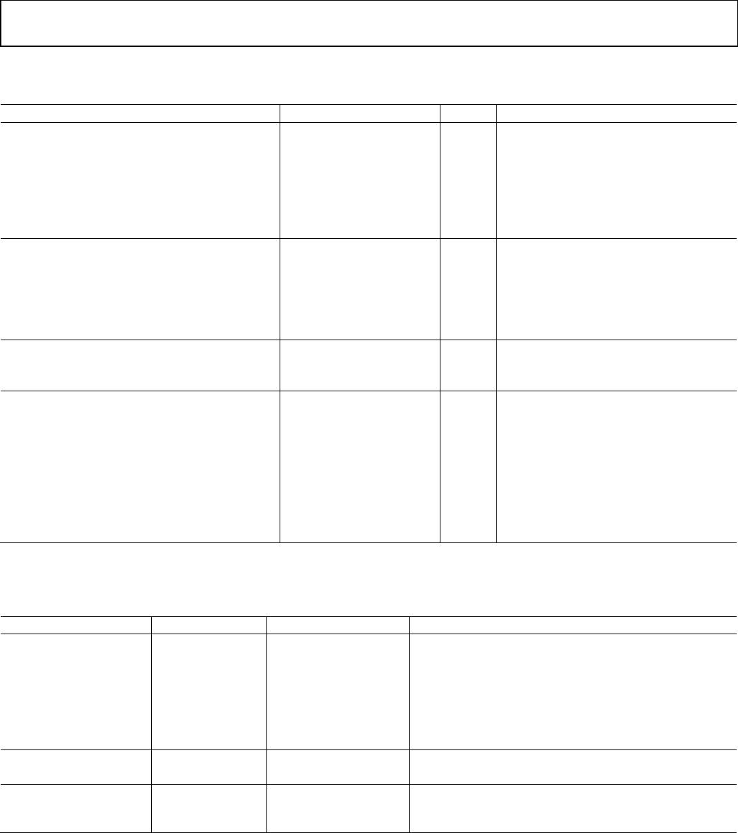
SYNC STATUS PIN
Table 8.
Parameter Min Typ Max Unit Test Conditions/Comments
Output Voltage High (V
OH
) 2.7 V
Output Voltage Low (V
OL
) 0.4 V
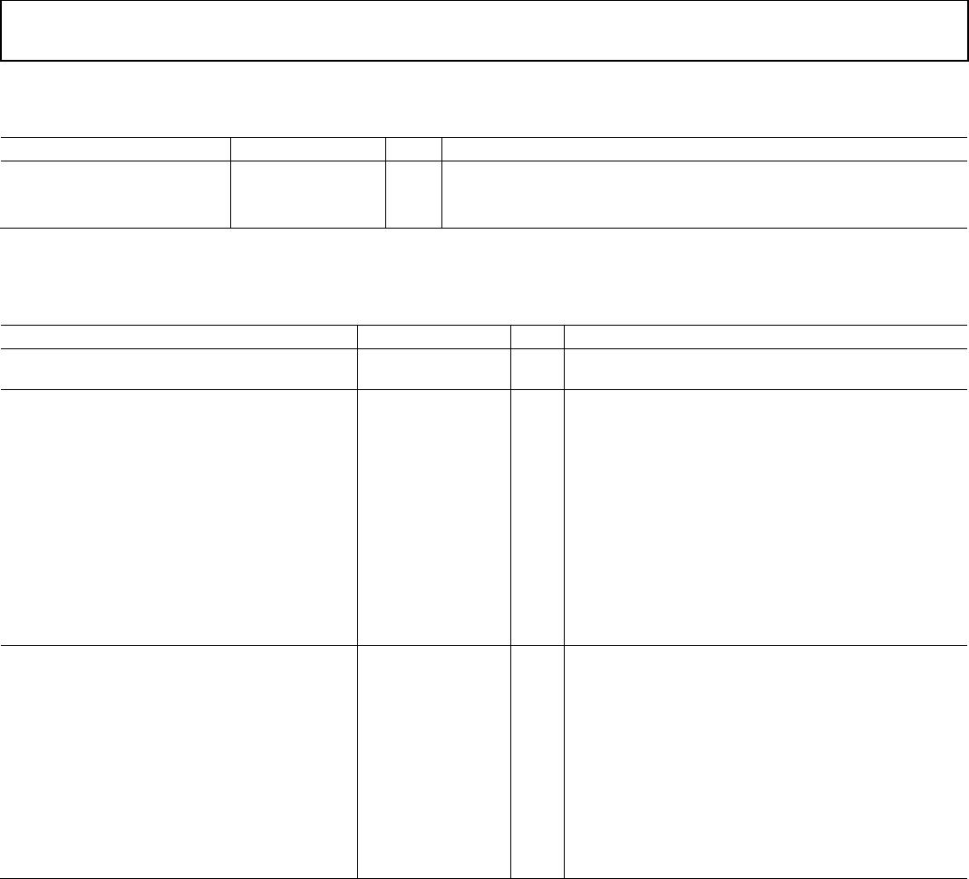
POWER
Table 9.
Parameter Min Typ Max Unit Test Conditions/Comments
POWER-UP DEFAULT MODE POWER DISSIPATION 550 600 mW Power-up default state; does not include power
dissipated in output load resistors. No clock.
POWER DISSIPATION 800 mW All outputs on. Three LVPECL outputs @ 800 MHz,
two CMOS out @ 62 MHz (5 pF load). Does not include
power dissipated in external resistors.
850 mW All outputs on. Three LVPECL outputs @ 800 MHz,
two CMOS out @ 125 MHz (5 pF load). Does not include
power dissipated in external resistors.
Full Sleep Power-Down 35 60 mW Maximum sleep is entered by setting 0x0A[1:0] = 01b
and 0x58[4] = 1b. This powers off all band gap
references. Does not include power dissipated in
terminations.
Power-Down (PDB) 60 80 mW Set FUNCTION pin for PDB operation by setting
0x58[6:5] = 11b. Pull PDB low. Does not include
power dissipated in terminations.
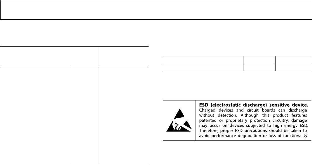
POWER DELTA
CLK1, CLK2 Power-Down 10 15 25 mW
Divider, DIV 2 to 32 to Bypass 23 27 33 mW For each divider.
LVPECL Output Power-Down (PD2, PD3) 50 65 75 mW For each output. Does not include dissipation
in termination (PD2 only).
LVDS Output Power-Down 80 92 110 mW For each output.
CMOS Output Power-Down (Static) 56 70 85 mW For each output. Static (no clock).
CMOS Output Power-Down (Dynamic) 115 150 190 mW For each CMOS output, single-ended. Clocking at
62 MHz with 5 pF load.
CMOS Output Power-Down (Dynamic) 125 165 210 mW For each CMOS output, single-ended. Clocking at
125 MHz with 5 pF load.