1
9
-
4
6
3
4
;
5
/
0
9
DS2780
Standalone Fuel Gauge IC
1 of 31
Note: Some revisions of this device may incorporate deviations from published specifications known as errata. Multiple revisions of any device
may be simultaneously available through various sales channels. For information about device errata, click here: www.maxim-ic.com/errata
.
www.maxim-ic.com
GENERAL DESCRIPTION
The DS2780 measures voltage, temperature and
current, and estimates available capacity for
rechargeable Lithium Ion and Lithium Ion Polymer
batteries. Cell characteristics and application
parameters used in the calculations are stored in on-
chip EEPROM. The available capacity registers
report a conservative estimate of the amount of
charge that can be removed given the current
temperature, discharge rate, stored charge and
application parameters. Capacity estimation reported
in mAh remaining and percentage of full.
APPLICATIONS
Digital Still Cameras
Sub-Notebook Computers
Handheld PC Data Terminals
3G Multimedia Wireless Handsets
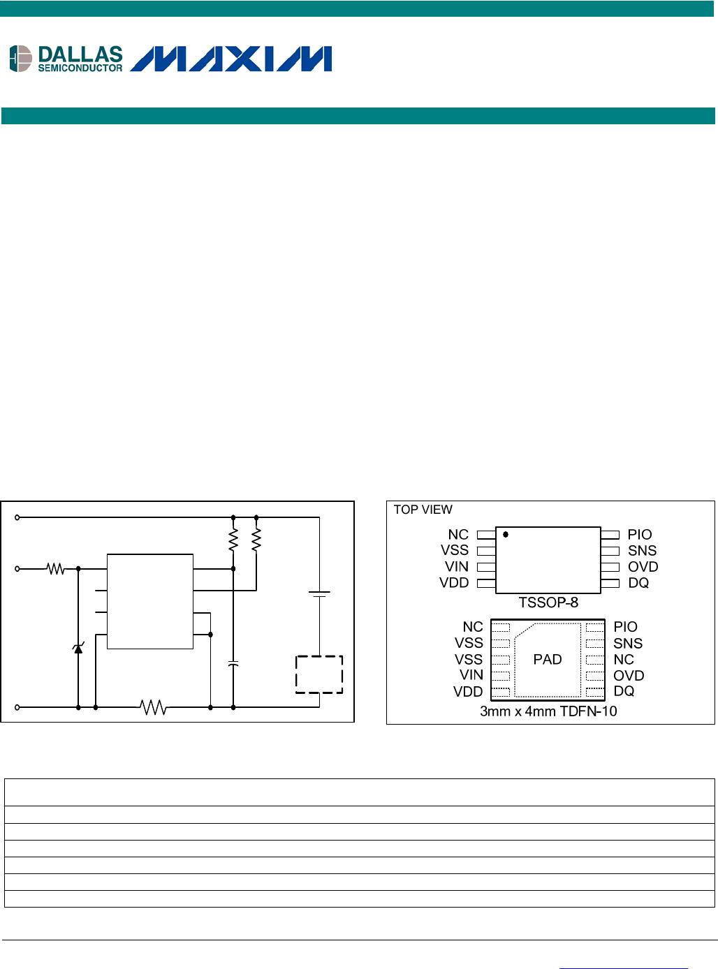
TYPICAL OPERATING CIRCUIT
FEATURES
Precision Voltage, Temperature, and Current
Measurement System
Internal Time Base is Accurate and Temperature
Stable
Absolute and Relative Capacity Estimated from
Coulomb Count, Discharge Rate, Temperature
and Battery Cell Characteristics
Accurate Warning of Low Battery Conditions
Automatic Backup of Coulomb Count and Age
Estimation to Nonvolatile (NV) EEPROM
Gain and Tempco Calibration Allows the Use of
Low-Cost Sense Resistors
24-Byte Battery/Application Parameter EEPROM
16-Byte User EEPROM
Unique ID and Multidrop 1-Wire
Interface
Tiny 8-pin TSSOP & 10-pin TDFN Package
Embeds Easily in Battery Packs Using Thin
Prismatic Cells
PIN CONFIGURATION
ORDERING INFORMATION
PART MARKING PACKAGE INFORMATION
DS2780E
2780 TSSOP
DS2780E/T&R 2780 TSSOP Tape-and-Reel
DS2780E+ 2780 TSSOP
DS2780E+T&R 2780 TSSOP Tape-and-Reel
DS2780G+ 2780 TDFN
DS2780G+T&R 2780 TDFN Tape-and-Reel
DQ 5
SNS 7
4
VDD
2 VSS
RSNS
PK+
PK-
DATA
Protection
Ci rc ui t
DS2780
PIO 8
150
1 Cell
Li-Ion
Battery
0.1uF
6 OVD
3 VIN
500
1K
NC 1
TSSOP-8
5.6V
+Denotes lead(Pb)-free/RoHS-compliant package.
1-Wire is a registered trademark of Maxim Integrated Products, Inc.
DS2780 Standalone Fuel Gauge IC
2 of 31
ABSOLUTE MAXIMUM RATINGS
Voltage Range on Any Pin Relative to VSS -0.3V to +6.0V
Voltage on VIN Relative to VSS -0.3V to (V
DD
+ 0.3V)
Operating Temperature Range
-40°C to +85°C
Storage Temperature Range
-55°C to +125°C
Soldering Temperature (10s)
See JEDEC J-STD-020
Stresses beyond those listed under “Absolute Maximum Ratings” may cause permanent damage to the device. These are stress ratings only,
and functional operation of the device at these or any other conditions beyond those indicated in the operational sections of the specifications is
not implied. Exposure to the absolute maximum rating conditions for extended periods may affect device reliability.
RECOMMENDED DC OPERATING CHARACTERISTICS
(VDD = 2.5V to 4.5V, T
A
= -20°C to +70°C, unless otherwise noted. Typical values are at T
A
= +25°C.)
PARAMETER SYMBOL CONDITIONS MIN TYP MAX UNITS
Supply Voltage VDD (Note 1) +2.5 +4.5 V
OVD Voltage (Note 1) -0.3 +4.5 V
DQ, PIO Voltage Range (Note 1) -0.3 +5.5 V
DC ELECTRICAL CHARACTERISTICS
(VDD = 2.5V to 4.5V, T
A
= -20°C to +70°C, unless otherwise noted. Typical values are at T
A
= +25°C.)
PARAMETER SYMBOL CONDITIONS MIN TYP MAX UNITS
2.5V VDD 4.2V 65 95
ACTIVE Current I
ACTIVE
105
µA
SLEEP Mode Current I
SLEEP
2.5V VDD 4.2V 1 3 µA
Input Logic High: DQ, PIO V
IH
(Note 1) 1.5 V
Input Logic Low: DQ, PIO V
IL
(Note 1) 0.6 V
Output Logic Low: DQ, PIO V
OL
I
OL
= 4mA (Note 1) 0.4 V
Pulldown Current: DQ, PIO I
PD
V
DQ
, V
PIO
= 0.4V 0.2 µA
Input Logic High: OVD V
IH
(Note 1)
VDD –
0.2
V
Input Logic Low: OVD V
IL
(Note 1) VSS + 0.2 V
VIN Input Resistance R
IN
15
M
DQ Capacitance C
DQ
50 pF
DQ SLEEP Timeout t
SLEEP
DQ < V
IL
(Note 5) 1.5 2.0 2.5 s
Undervoltage SLEEP
Threshold
V
SLEEP
(Note 1) 2.40 2.45 2.50 V
ELECTRICAL CHARACTERISTICS: TEMPERATURE, VOLTAGE, CURRENT
(V
CC
= 2.5V to 4.5V, T
A
= -20°C to +70°C, unless otherwise noted. Typical values are at T
A
= +25°C.)
PARAMETER SYMBOL CONDITIONS MIN TYP MAX UNITS
Temperature Resolution T
LSB
0.125 °C
Temperature Error T
ERR
±3 °C
Voltage Resolution V
LSB
4.88 mV
Voltage Full-Scale V
FS
0 4.992 V
Voltage Error V
ERR
±50 mV
Current Resolution I
LSB
1.56 µV
DS2780 Standalone Fuel Gauge IC
3 of 31
PARAMETER SYMBOL CONDITIONS MIN TYP MAX UNITS
Current Full-Scale I
FS
±51.2 mV
Current Gain Error I
GERR
(Note 2) ±1
% Full-
Scale
Current Offset Error I
OERR
0°C T
A
+70°C,
2.5V VDD 4.2V
(Note 4)
-7.82 +12.5 µV
Accumulated Current Offset q
OERR
0°C T
A
+70°C,
2.5V VDD 4.2V
VSNS = VSS, (Notes 3,
4)
-188 +0
µVhr/
day
VDD = 3.8V, T
A
= +25°C ±1
0°C T
A
+70°C,
2.5V VDD 4.2V
±2
Timebase Error t
ERR
±3
%
ELECTRICAL CHARACTERISTICS: 1-WIRE INTERFACE, STANDARD
(V
CC
= 2.5V to 4.5V, T
A
= -20°C to +70°C.)
PARAMETER SYMBOL CONDITIONS MIN TYP MAX UNITS
Time Slot t
SLOT
60 120
s
Recovery Time t
REC
1
s
Write-0 Low Time t
LOW0
60 120
s
Write-1 Low Time t
LOW1
1 15
s
Read Data Valid t
RDV
15
s
Reset Time High t
RSTH
480
s
Reset Time Low t
RSTL
480 960
s
Presence Detect High t
PDH
15 60
s
Presence Detect Low t
PDL
60 240
s
ELECTRICAL CHARACTERISTICS: 1-WIRE INTERFACE, OVERDRIVE
(V
CC
= 2.5V to 4.5V, T
A
= -20°C to +70°C.)
PARAMETER SYMBOL CONDITIONS MIN TYP MAX UNITS
Time Slot t
SLOT
6 16
s
Recovery Time t
REC
1
s
Write-0 Low Time t
LOW0
6 16
s
Write-1 Low Time t
LOW1
1 2
s
Read Data Valid t
RDV
2
s
Reset-Time High t
RSTH
48
s
Reset-Time Low t
RSTL
48 80
s
Presence-Detect High t
PDH
2 6
s
Presence-Detect Low t
PDL
8 24
s

DS2780G+

Mfr. #:
Manufacturer:
Maxim Integrated
Description:
Battery Management Stand-Alone Fuel Gauge
Lifecycle:
New from this manufacturer.
Delivery:
DHL FedEx Ups TNT EMS
Payment:
T/T Paypal Visa MoneyGram Western Union

Products related to this Datasheet