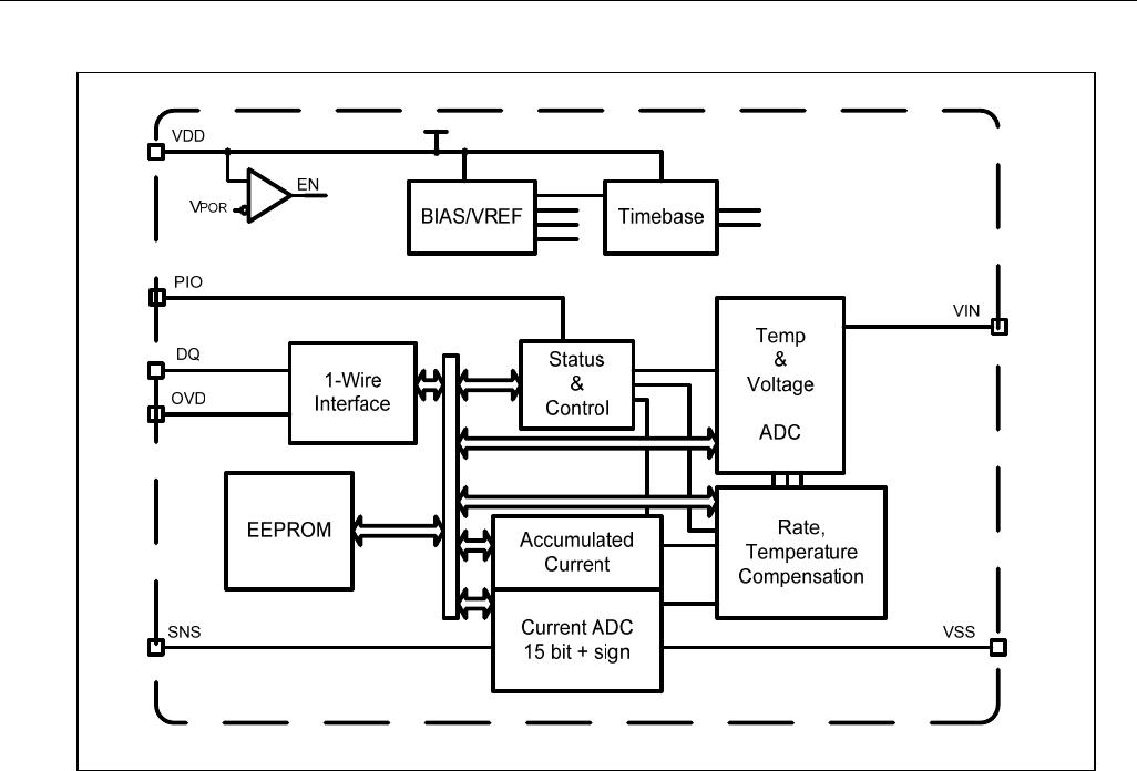
DS2780 Standalone Fuel Gauge IC
4 of 31
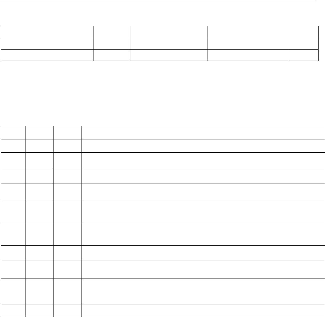
EEPROM RELIABILITY SPECIFICATION
(V
CC
= 2.5V to 4.5V, T
A
= -20°C to +70°C, unless otherwise noted. Typical values are at T
A
= +25°C.)
PARAMETER SYMBOL CONDITIONS MIN TYP MAX UNITS
EEPROM Copy Time t
EEC
10 ms
EEPROM Copy Endurance N
EEC
T
A
= +50°C 50,000 cycles
Note 1: All voltages are referenced to VSS.
Note 2: Factory calibrated accuracy. Higher accuracy can be achieved by in-system calibration by the user.
Note 3: Accumulation bias register set to 00h.
Note 4: Parameters guaranteed by design.
Note 5: The application must wait for the maximum DQ SLEEP Timeout to confirm that the IC has entered sleep
mode.
PIN DESCRIPTION
NAME
TSSOP
PIN
TDFN
PIN
FUNCTION
NC 1 1 Not Connected. Pin not connected internally, float or connect to VSS.
VSS 2 2, 3
Device Ground. Connect directly to the negative terminal of the battery cell. Connect
the sense resistor between VSS and SNS.
VIN 3 4
Voltage Sense Input. The voltage of the battery cell is monitored through this input
pin.
VDD 4 5
Power-Supply Input. Connect to the positive terminal of the battery cell through a
decoupling network.
DQ 5 6
Data Input/Output. 1-Wire data line. Open-drain output driver. Connect this pin to the
DATA terminal of the battery pack. This pin has a weak internal pulldown (I
PD
) for
sensing pack disconnection from host or charger.
OVD 6 7
1-Wire Bus Speed Control.
Input logic level selects the speed of the 1-Wire bus.
Logic 1 selects overdrive (OVD) and Logic 0 selects standard timing (STD). On a
multidrop bus, all devices must operate at the same speed.
NC — 8 Not Connected. Pin not connected internally, float or connect to VSS.
SNS 7 9
Sense Resistor Connection. Connect to the negative terminal of the battery pack.
Connect the sense resistor between VSS and SNS.
PIO 8 10
Programmable I/O Pin. Can be configured as input or output to monitor or control
user-defined external circuitry. Output driver is open drain. This pin has an weak
internal pulldown (I
PD
).
PAD — PAD Exposed Pad. Connect to VSS or leave floating. (Only present on TDFN package)