DS2780 Standalone Fuel Gauge IC
7 of 31
fuel gauge data to EEPROM, but some data loss can occur depending on the timing of the protection event and the
backup. When the protection circuit is connected directly to the battery the protection is absolute, no charging will
occur during a protection event. With the protection circuit located outside, see Figure 3, the DS2780 will remain
powered up during a protection event. The disadvantage to this configuration is that you run the risk of
overcharging the battery by creating an unintentional charge path from PK+ to DATA or PIO (V
PK+
> V
CELL
+ V
DIODE
).
Communication to the DS2780 is broken during a protection event regardless of protector location.
POWER MODES
The DS2780 has two power modes: ACTIVE and SLEEP. On initial power up, the DS2780 defaults to ACTIVE
mode. While in ACTIVE mode, the DS2780 is fully functional with measurements and capacity estimation
continuously updated. In SLEEP mode, the DS2780 conserves power by disabling measurement and capacity
estimation functions, but preserves register contents. SLEEP mode is entered under two different conditions and
an enable bit for each condition makes entry into SLEEP optional. SLEEP mode can be enabled using the Power
Mode (PMOD) bit or the Under Voltage Enable (UVEN) bit.
The PMOD type SLEEP is entered if the PMOD bit is set AND DQ is low for t
SLEEP
(2s nominal). The condition of
DQ low for t
SLEEP
can be used to detect a pack disconnection or system shutdown, in which no charge or discharge
current will flow. A PMOD SLEEP condition transitions back to ACTIVE mode when DQ is pulled high.
The second option for entering SLEEP is an under voltage condition. When the UVEN bit is set, the DS2780
transitions to SLEEP if the voltage on VIN is less than V
SLEEP
(2.45V nominal) AND DQ is stable at a low or high
logic level for t
SLEEP
. An under-voltage condition occurs when a pack is fully discharged, where loading on the
battery should be minimized. UVEN type SLEEP relieves the battery of the I
ACTIVE
load until communication on DQ
resumes.
NOTE: PMOD and UVEN SLEEP features must be disabled when a battery is charged on an external charger that
does not connect to the DQ pin. PMOD SLEEP can be used if the charger pulls DQ high. UVEN SLEEP can be
used if the charger toggles DQ. The DS2780 remains in SLEEP on a charger that fails to properly drive DQ and
therefore does not measure or accumulate current when a battery is charged.
INITIATING COMMUNICATION IN SLEEP
When beginning communication with a DS2780 in PMOD SLEEP, DQ must be pulled up first and then a 1-Wire
Reset pulse must be issued by the master. In UVEN SLEEP, the procedure depends on the state of DQ when
UVEN SLEEP was entered. If DQ was low, DQ must be pulled up and then a 1-Wire Reset pulse must be issued
by the master as with PMOD SLEEP. If DQ was high when UVEN SLEEP was entered, then the DS2780 is
prepared to receive a 1-Wire reset from the master. In the first two cases with DQ low during SLEEP, the DS2780
does not respond to the first rising edge of DQ with a presence pulse.
VOLTAGE MEASUREMENT
Battery voltage is measured at the VIN input with respect to VSS. It has a range of 0V to 4.992V (pin voltage
limited to 4.5V) and a resolution of 4.88mV. The measurement is stored in the VOLTAGE register in two’s
compliment form and is updated every 440ms. Voltages above the maximum register value are reported at the
maximum value; voltages below the minimum register value are reported at the minimum value. The format of the
voltage register is shown in Figure 4.
Figure 4. Voltage Register Format
VOLT
Read Only
MSB—Address 0Ch LSB—Address 0Dh
S 2
9
2
8
2
7
2
6
2
5
2
4
2
3
2
2
2
1
2
0
X X X X X
MSb LSb MSb LSb
“S”: sign bit(s), “X”: reserved
Units: 4.88mV
DS2780 Standalone Fuel Gauge IC
8 of 31
VIN is usually connected to the positive terminal of a single cell Lithium-Ion battery via a 1k resistor. The input
impedance is large enough (15M) to be connected to a high impedance voltage divider in order to support
multiple cell applications. The pack voltage should be divided by the number of series cells to present a single cell
average voltage to the VIN input. In Figure 2, the value of R can be up to 1M without incurring significant error
due to input loading.
TEMPERATURE MEASUREMENT
The DS2780 uses an integrated temperature sensor to measure battery temperature with a resolution of 0.125°C.
Temperature measurements are updated every 440ms and placed in the temperature register in two’s complement
form. The format of the temperature register is shown in Figure 5.
Figure 5. Temperature Register Format
TEMP
Read Only
MSB—Address 0Ah LSB—Address 0Bh
S 2
9
2
8
2
7
2
6
2
5
2
4
2
3
2
2
2
1
2
0
X X X X X
MSb LSb MSb LSb
“S”: sign bit(s), “X”: reserved
Units: 0.125C
CURRENT MEASUREMENT
In the ACTIVE mode of operation, the DS2780 continually measures the current flow into and out of the battery by
measuring the voltage drop across a low-value current-sense resistor, R
SNS
. The voltage-sense range between
SNS and VSS is ±51.2mV. The input linearly converts peak signal amplitudes up to 102.4mV as long as the
continuous signal level (average over the conversion cycle period) does not exceed ±51.2mV. The ADC samples
the input differentially at 18.6kHz and updates the Current register at the completion of each conversion cycle.
The Current register is updated every 3.515s with the current conversion result in two’s complement form. Charge
currents above the maximum register value are reported at the maximum value (7FFFh = +51.2mV). Discharge
currents below the minimum register value are reported at the minimum value (8000h = -51.2mV).
Figure 6. Current Register Format
CURRENT
Read Only
MSB—Address 0Eh LSB—Address 0Fh
S 2
14
2
13
2
12
2
11
2
10
2
9
2
8
2
7
2
6
2
5
2
4
2
3
2
2
2
1
2
0
MSb LSb MSb LSb
“S”: sign bit(s)
Units: 1.5625V/Rsns
CURRENT RESOLUTION (1 LSB)
R
SNS
VSS
-
VSNS
20m 15m 10m 5m
1.5625V 78.13A 104.2A 156.3A 312.5A
DS2780 Standalone Fuel Gauge IC
9 of 31
AVERAGE CURRENT MEASUREMENT
The Average Current register reports an average current level over the preceding 28 seconds. The register value is
updated every 28s in two’s complement form, and is the average of the 8 preceding Current register updates. The
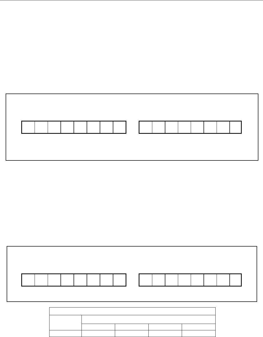
format of the Average Current register is shown in Figure 7. Charge currents above the maximum register value
are reported at the maximum value (7FFFh = +51.2mV). Discharge currents below the minimum register value are
reported at the minimum value (8000h = -51.2mV).
Figure 7. Average Current Register Format
IAVG
Read Only
MSB—Address 08h LSB—Address 09h
S 2
14
2
13
2
12
2
11
2
10
2
9
2
8
2
7
2
6
2
5
2
4
2
3
2
2
2
1
2
0
MSb LSb MSb LSb
“S”: sign bit(s)
Units: 1.5625V/Rsns
CURRENT OFFSET CORRECTION
Every 1024th conversion, the ADC measures its input offset to facilitate offset correction. Offset correction occurs
approximately once per hour. The resulting correction factor is applied to the subsequent 1023 measurements.
During the offset correction conversion, the ADC does not measure the sense resistor signal. A maximum error of
1/1024 in the accumulated current register (ACR) is possible; however, to reduce the error, the current
measurement made just prior to the offset conversion is displayed in the current register and is substituted for the
dropped current measurement in the current accumulation process. This results in an accumulated current error
due to offset correction of less than 1/1024.
CURRENT MEASUREMENT CALIBRATION
The DS2780’s current measurement gain can be adjusted through the RSGAIN register, which is factory-calibrated
to meet the data sheet specified accuracy. RSGAIN is user accessible and can be reprogrammed after module or
pack manufacture to improve the current measurement accuracy. Adjusting RSGAIN can correct for variation in an
external sense resistor’s nominal value, and allows the use of low-cost, non-precision current sense resistors.
RSGAIN is an 11 bit value stored in 2 bytes of the Parameter EEPROM Memory Block. The RSGAIN value adjusts
the gain from 0 to 1.999 in steps of 0.001 (precisely 2
-10
). The user must program RSGAIN cautiously to ensure
accurate current measurement. When shipped from the factory, the gain calibration value is stored in two separate
locations in the Parameter EEPROM Block, RSGAIN which is reprogrammable and FRSGAIN which is read only.
RSGAIN determines the gain used in the current measurement. The read-only FRSGAIN is provided to preserve
the factory value only and is not used in the current measurement.
SENSE RESISTOR TEMPERATURE COMPENSATION
The DS2780 is capable of temperature compensating the current sense resistor to correct for variation in a sense
resistor’s value over temperature. The DS2780 is factory programmed with the sense resistor temperature
coefficient, RSTC, set to zero, which turns off the temperature compensation function. RSTC is user accessible
and can be reprogrammed after module or pack manufacture to improve the current accuracy when using a high
temperature coefficient current-sense resistor. RSTC is an 8-bit value stored in the Parameter EEPROM Memory
Block. The RSTC value sets the temperature coefficient from 0 to +7782ppm/ºC in steps of 30.5ppm/ºC. The user
must program RSTC cautiously to ensure accurate current measurement.
Temperature compensation adjustments are made when the Temperature register crosses 0.5
o
C boundaries. The
temperature compensation is most effective with the resistor placed as close as possible to the VSS terminal. This
will optimize thermal coupling of the resistor to the on-chip temperature sensor. The current shunt trace should be
run under the DS2780 package, and it should be constructed with a copper PCB trace.
CURRENT ACCUMULATION
Current measurements are internally summed, or accumulated, at the completion of each conversion period and
the results are stored in the Accumulated Current Register (ACR). The accuracy of the ACR is dependent on the

DS2780G+

Mfr. #:
Manufacturer:
Maxim Integrated
Description:
Battery Management Stand-Alone Fuel Gauge
Lifecycle:
New from this manufacturer.
Delivery:
DHL FedEx Ups TNT EMS
Payment:
T/T Paypal Visa MoneyGram Western Union

Products related to this Datasheet