DS2780 Standalone Fuel Gauge IC
10 of 31
current measurement and the conversion timebase. The ACR has a range of 0 to 409.6mVh with an LSb of
6.25Vh. Additional read-only registers (ACRL) hold fractional results of each accumulation to avoid truncation
errors. Accumulation of charge current above the maximum register value is reported at the maximum register
value (7FFFh); conversely, accumulation of discharge current below the minimum register value is reported at the
minimum value (8000h).
Charge currents (positive Current register values) less than 100V are not accumulated in order to mask the effect
of accumulating small positive offset errors over long periods. This limits the minimum charge current, for coulomb-
counting purposes, to 5mA for RSNS = 0.020 and 20mA for RSNS = 0.005.
Read and write access is allowed to the ACR. The ACR must be written MSByte first then LSByte. The write must
be completed within 3.515s (one ACR register update period). A write to the ACR forces the ADC to perform an
offset correction conversion and update the internal offset correction factor. Current measurement and
accumulation begins with the second conversion following a write to the ACR. Writing the ACR clears the fractional
values in the ACRL. The format of the ACR is shown in Figure 8, and the ACRL is shown in Figure 9.
To preserve the ACR value in case of power loss, it is backed up to EEPROM. The ACR value is recovered from
EEPROM on power-up. See the Memory Map in Table 2 for specific address location and backup frequency.
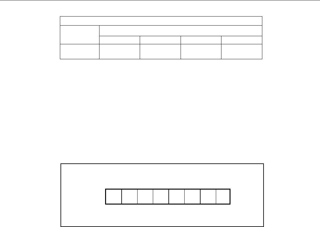
Figure 8. Accumulated Current Register Format, ACR
ACR
R/W & EE
MSB—Address 10h LSB—Address 11h
2
15
2
14
2
13
2
12
2
11
2
10
2
9
2
8
2
7
2
6
2
5
2
4
2
3
2
2
2
1
2
0
MSb LSb MSb LSb
Units: 6.25Vh/Rsns
Figure 9. Fractional/Low Accumulated Current Register Format, ACRL
ACRL
Read Only
MSB—Address 12h LSB—Address 13h
2
11
2
10
2
9
2
8
2
7
2
6
2
5
2
4
2
3
2
2
2
1
2
0
X X X X
MSb LSb MSb LSb
“X”: reserved Units:1.526nVHr/R
SNS
ACR LSb
R
SNS
VSS
-
VSNS
20m 15m 10m 5m
6.25Vh 312.5Ah 416.7Ah 625Ah
1.250mAh
DS2780 Standalone Fuel Gauge IC
11 of 31
ACR RANGE
R
SNS
VSS
-
VSNS
20m 15m 10m 5m
±409.6mVh ±20.48Ah ±27.30Ah ±40.96Ah ±81.92Ah
ACCUMULATION BIAS
The Accumulation Bias register (AB) allows an arbitrary bias to be introduced into the current-accumulation
process. The AB can be used to account for currents that do not flow through the sense resistor, estimate currents
too small to measure, estimate battery self-discharge or correct for static offset of the DS2780. The AB register
allows a user programmed constant positive or negative polarity bias to be included in the current accumulation
process. The user-programmed two’s compliment value, with bit weighting the same as the current register, is
added to the ACR once per current conversion cycle. The AB value is loaded on power-up from EEPROM. The
format of the AB register is shown in Figure 10.
Figure 10. Accumulation Bias Register Formats
AB
EE
Address 61h
S 2
6
2
5
2
4
2
3
2
2
2
1
2
0
MSb LSb
“S”: sign bit Units: 1.5625V/Rsns
CAPACITY ESTIMATION ALGORITHM
Remaining capacity estimation uses real-time measured values, stored parameters describing the cell
characteristics, and application operating limits. The following diagram describes the algorithm inputs and outputs.
DS2780 Standalone Fuel Gauge IC
12 of 31
Figure 11. Top Level Algorithm Diagram
MODELING CELL CHARACTERISTICS
In order to achieve reasonable accuracy in estimating remaining capacity, the cell performance characteristics over
temperature, load current, and charge termination point must be considered. Since the behavior of Li-ion cells is
non-linear, even over a limited temperature range of 10°C to 35°C, these characteristics must be included in the
capacity estimation to achieve a reasonable accuracy. See Applications Note AN131 “Li+ Fuel Gauging with Dallas
Semiconductor Devices” for general information on the FuelPack™ method used in the DS2780. To facilitate
efficient implementation in hardware, a modified version of the method outlined in AN131 is used to store cell
characteristics in the DS2780. Full and empty points are retrieved in a lookup process which re-traces a piece-wise
linear model. Three model curves are stored: Full, Active Empty and Standby Empty. Each model curve is
constructed with 4 line segments and spans from 0°C to 40°C. Operation outside the 0°C to 40°C model span is
supported by the model with minimal loss of accuracy. Above 40°C, the 40°C fixed points are extended with zero
slope. This achieves a conservative capacity estimate for temperatures above 40°C. Below 0°C, the model curves
are extended using the slope of each 0°C to 10°C segment. If low temperature operation is expected, the 0°C to
10°C slopes can be selected to optimize the model accuracy. A diagram of example battery cell model curves is
shown in Figure 12.
FuelPack is a trademark of Maxim Integrated Products, Inc.

DS2780G+

Mfr. #:
Manufacturer:
Maxim Integrated
Description:
Battery Management Stand-Alone Fuel Gauge
Lifecycle:
New from this manufacturer.
Delivery:
DHL FedEx Ups TNT EMS
Payment:
T/T Paypal Visa MoneyGram Western Union

Products related to this Datasheet