IDT 89HPES24NT24G2 Datasheet
10 of 35 December 17, 2013
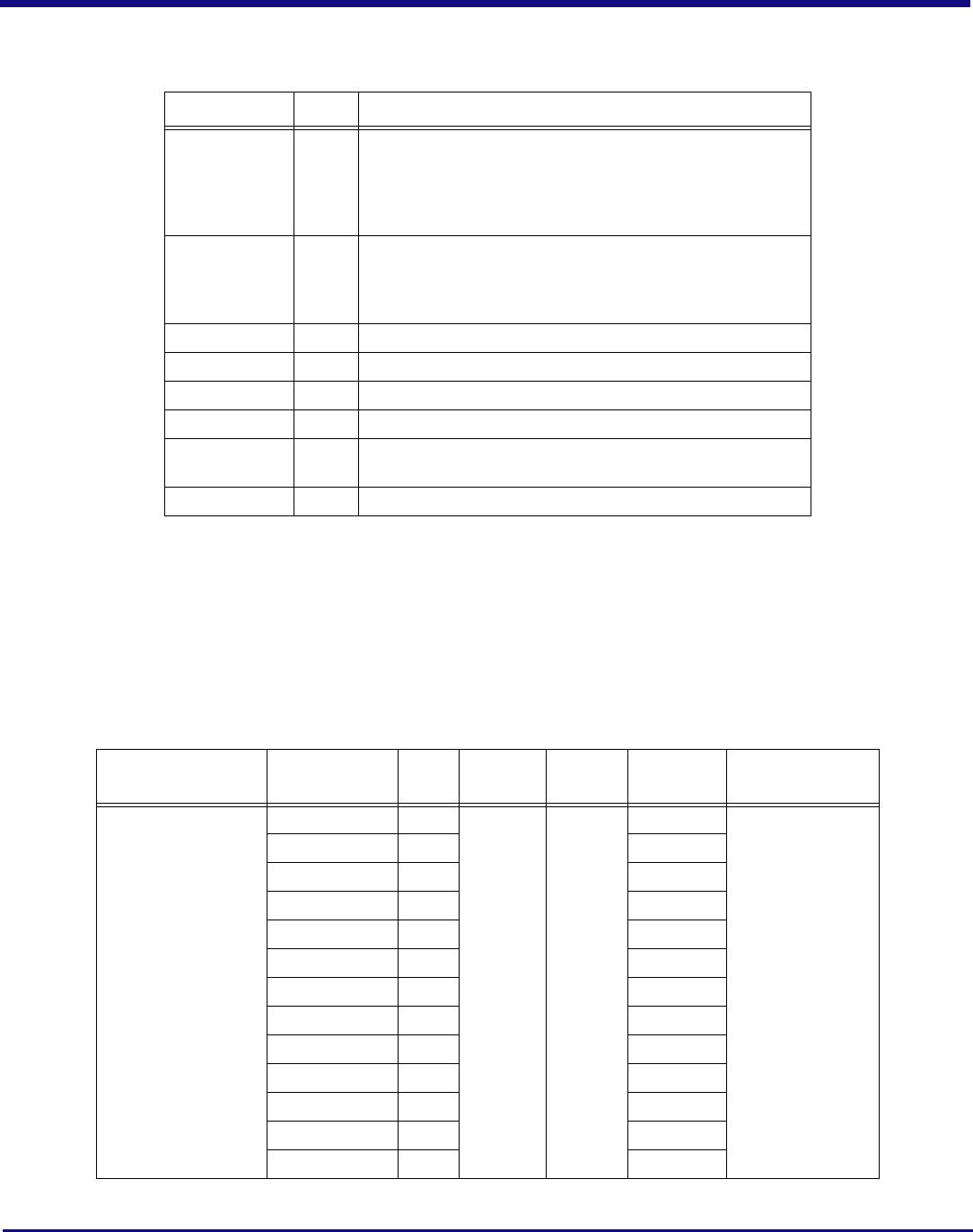
PERSTN I Fundamental Reset. Assertion of this signal resets all logic inside the device.
RSTHALT I Reset Halt. When this signal is asserted during a switch fundamental reset sequence,
the switch remains in a quasi-reset state with the Master and Slave SMBuses active.
This allows software to read and write registers internal to the device before normal
device operation begins. The device exits the quasi-reset state when the RSTHALT bit
is cleared in the SWCTL register by an SMBus master.
SWMODE[3:0] I Switch Mode. These configuration pins determine the switch operating mode.
These pins should be static and not change following the negation of PERSTN.
0x0 - Single partition
0x1 - Single partition with Serial EEPROM initialization
0x2 - Single partition with Serial EEPROM Jump 0 initialization
0x3 - Single partition with Serial EEPROM Jump 1 initialization
0x4 through 0x7 - Reserved
0x8 - Single partition with reduced latency
0x9 - Single partition with Serial EEPROM initialization and reduced latency
0xA - Multi-partition with Unattached ports
0xB - Multi-partition with Unattached ports and I
2
C Reset
0xC - Multi-partition with Unattached ports and Serial EEPROM initialization
0xD - Multi-partition with Unattached ports with I
2
C Reset and Serial EEPROM initial-
ization
0xE - Multi-partition with Disabled ports
0xF - Multi-partition with Disabled ports and Serial EEPROM initialization
Signal Type Name/Description
JTAG_TCK I JTAG Clock. This is an input test clock used to clock the shifting of data into or out of
the boundary scan logic or JTAG Controller. JTAG_TCK is independent of the system
clock with a nominal 50% duty cycle.
JTAG_TDI I JTAG Data Input. This is the serial data input to the boundary scan logic or JTAG
Controller.
JTAG_TDO O JTAG Data Output. This is the serial data shifted out from the boundary scan logic or
JTAG Controller. When no data is being shifted out, this signal is tri-stated.
JTAG_TMS I JTAG Mode. The value on this signal controls the test mode select of the boundary
scan logic or JTAG Controller.
JTAG_TRST_N I JTAG Reset. This active low signal asynchronously resets the boundary scan logic
and JTAG TAP Controller. An external pull-up on the board is recommended to meet
the JTAG specification in cases where the tester can access this signal. However, for
systems running in functional mode, one of the following should occur:
1) actively drive this signal low with control logic
2) statically drive this signal low with an external pull-down on the board
Table 8 Test Pins
Signal Type Name/Description
Table 7 System Pins (Part 2 of 2)
IDT 89HPES24NT24G2 Datasheet
11 of 35 December 17, 2013
Pin Characteristics
Note: Some input pads of the switch do not contain internal pull-ups or pull-downs. Unused SMBus and System inputs should be tied off to
appropriate levels. This is especially critical for unused control signal inputs which, if left floating, could adversely affect operation. Also, floating
pins can cause a slight increase in power consumption. Unused Serdes (Rx and Tx) pins should be left floating. Finally, No Connection pins
should not be connected.
Signal Type Name/Description
REFRES[7:0] External Reference Resistor. Reference for the corresponding SerDes
bias currents and PLL calibration circuitry. A 3K Ohm +/- 1% resistor should
be connected from this pin to ground and isolated from any source of noise
injection. Each bit of this signal corresponds to a SerDes quad, e.g.,
REFRES[5] is the reference resistor for SerDes quad 5.
REFRESPLL PLL External Reference Resistor. Provides a reference for the PLL bias
currents and PLL calibration circuitry. A 3K Ohm +/- 1% resistor should be
connected from this pin to ground and isolated from any source of noise
injection.
V
DD
CORE Core V
DD.
Power supply for core logic (1.0V).
V
DD
I/O I/O V
DD.
LVTTL I/O buffer power supply (3.3V).
V
DD
PEA PCI Express Analog Power. Serdes analog power supply (1.0V).
V
DD
PEHA PCI Express Analog High Power. Serdes analog power supply (2.5V).
V
DD
PETA PCI Express Transmitter Analog Voltage. Serdes transmitter analog
power supply (1.0V).
V
SS
Ground.
Table 9 Power, Ground, and SerDes Resistor Pins
Function Pin Name Type Buffer
I/O
Type
Internal
Resistor
1
Notes
PCI Express Interface PE00RN[0] I PCIe
differential
2
Serial Link Note: Unused SerDes
pins can be left floating
PE00RP[0] I
PE00TN[0] O
PE00TP[0] O
PE01RN[0] I
PE01RP[0] I
PE01TN[0] O
PE01TP[0] O
PE02RN[0] I
PE02RP[0] I
PE02TN[0] O
PE02TP[0] O
PE03RN[0] I
Table 10 Pin Characteristics (Part 1 of 5)
IDT 89HPES24NT24G2 Datasheet
12 of 35 December 17, 2013
PCI Express Interface
(cont.)
PE03RP[0] I PCIe
differential
Serial Link
PE03TN[0] O
PE03TP[0] O
PE04RN[0] I
PE04RP[0] I
PE04TN[0] O
PE04TP[0] O
PE05RN[0] I
PE05RP[0] I
PE05TN[0] O
PE05TP[0] O
PE06RN[0] I
PE06RP[0] I
PE06TN[0] O
PE06TP[0] O
PE07RN[0] I
PE07RP[0] I
PE07TN[0] O
PE07TP[0] O
PE08RN[0] I
PE08RP[0] I
PE08TN[0] O
PE08TP[0] O
PE09RN[0] I
PE09RP[0] I
PE09TN[0] O
PE09TP[0] O
PE10RN[0] I
PE10RP[0] I
PE10TN[0] O
PE10TP[0] O
PE11RN[0] I
PE11RP[0] I
PE11TN[0] O
PE11TP[0] O
PE12RN[0] I
PE12RP[0] I
Function Pin Name Type Buffer
I/O
Type
Internal
Resistor
1
Notes
Table 10 Pin Characteristics (Part 2 of 5)

89H24NT24G2ZCHLGI

Mfr. #:
Manufacturer:
IDT
Description:
PCI Interface IC PCIE SWITCH
Lifecycle:
New from this manufacturer.
Delivery:
DHL FedEx Ups TNT EMS
Payment:
T/T Paypal Visa MoneyGram Western Union