LTC5569
9
5569fb
For more information www.linear.com/LTC5569
PIN FUNCTIONS
RFA/RFB (Pin 1/Pin 4): Single-Ended RF Inputs for the
A and B Mixers, Respectively. These pins are internally
connected to the primary winding of the integrated RF
transformers, which have low DC resistance to ground.
Series DC-blocking capacitors must be used if the RF
sources have DC voltage present. The RF inputs are 50Ω
impedance matched from 1.4GHz to 3.3GHz, as long as
the mixer is enabled. Operation down to 300MHz or up
to 4GHz is possible with external matching.
GND (Pins 2, 3, 10, Exposed Pad Pin 17): Ground. These
pins must be soldered to the RF ground plane on the circuit
board. The exposed pad metal of the package provides
both electrical contact to ground and good thermal contact
to the printed circuit board.
LO (Pin 11): Single-Ended Local Oscillator Input. This
pin is internally connected to the primary winding of an
integrated transformer, which has low DC resistance to
ground. A series DC-blocking capacitor must be used
to avoid damage to the internal transformer. This input
is 50Ω impedance matched from 1GHz to 3.5GHz, even
when one or both mixers are disabled. Operation down
to 350MHz or up to 4500MHz is possible with external
matching.
ENA/ENB (Pin 12/Pin 9): Enable Pins for the A and B Mixers,
Respectively. When the input voltage is greater than 2.5V,
the mixer is enabled. When the input voltage is less than
0.3V, the mixer is disabled. Typical input current is less
than 30µA. These pins have internal pull-down resistors.
V
CCA
/V
CCB
(Pin 13/Pin 8): Power Supply Pins for the A and
B Mixers, Respectively. These pins must be connected to
a regulated 3.3V supply, with bypass capacitors located
close to the pins. Typical DC current consumption is
34mA, each.
IFA
+
/IFA
–
(Pin 15/Pin 14), IFB
+
/IFB
–
(Pin 6/Pin 7): Open-
Collector Differential IF Outputs for the A and B Mixers,
Respectively. These pins must be connected to the V
CC
supply through impedance-matching inductors or a
transformer center tap. Typical DC current consumption
is 28mA into each pin.
BIASA/BIASB (Pin 16/Pin 5): These pins allow adjustment
of the mixer DC supply currents for mixers A and B, respec
-
tively. Typical, open-circuit DC voltage is 2.2V. These pins
should be left open circuited for optimum performance.
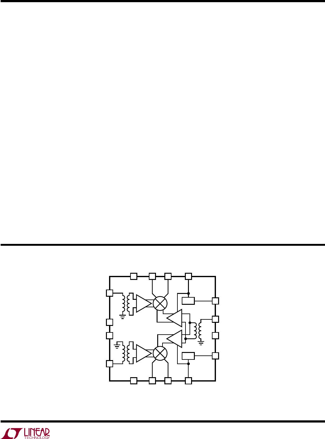
BLOCK DIAGRAM
RFA
GND
GND
RFB
ENA
ENB
5569 BD
V
CCA
BIASA
BIASB
V
CCB
IFA
–
IFA
+
IFB
+
IFB
–
BIAS
RF
BIAS
LO
LO
RF
1
13
12
LO
11
9
8
16 1415
5 76
2
3
GND
10
4

