DS1374
After the DS1374 acknowledges the slave address
+ write bit, the master transmits a register address
to the DS1374. This sets the register pointer on the
DS1374, with the DS1374 acknowledging the trans-
fer. The master can then transmit zero or more
bytes of data, with the DS1374 acknowledging
each byte received. The register pointer increments
after each data byte is transferred. The master gen-
erates a STOP condition to terminate the data write.
Slave Transmitter Mode (Read Mode): The first
byte is received and handled as in the slave receiv-
er mode. However, in this mode, the direction bit
indicates that the transfer direction is reversed.
Serial data is transmitted on SDA by the DS1374,
while the serial clock is input on SCL. START and
STOP conditions are recognized as the beginning
and end of a serial transfer. Address recognition is
performed by hardware after reception of the slave
address and direction bit. The slave address byte
is the first byte received after the START condition
is generated by the master. The slave address byte
contains the 7-bit DS1374 address, which is
1101000, followed by the direction bit (R/W), which
is 1 for a read. After receiving and decoding the
slave address byte, the DS1374 outputs an
acknowledge on SDA. The DS1374 then begins to
transmit data starting with the register address
pointed to by the register pointer. If the register
pointer is not written to before the initiation of a
read mode, the first address that is read is the last
one stored in the register pointer. The DS1374 must
receive a not acknowledge to end a read.
Handling, PC Board Layout, and
Assembly
The DS1374C package contains a quartz tuning-fork
crystal. Pick-and-place equipment can be used, but
precautions should be taken to ensure that excessive
shocks are avoided. Ultrasonic cleaning should be
avoided to prevent damage to the crystal.
Avoid running signal traces under the package, unless
a ground plane is placed between the package and the
signal line. All no connect (N.C.) pins must be connect-
ed to ground.
Moisture-sensitive packages are shipped from the facto-
ry dry-packed. Handling instructions listed on the pack-
age label must be followed to prevent damage during
reflow. Refer to the IPC/JEDEC J-STD-020 standard for
moisture-sensitive device (MSD) classifications.
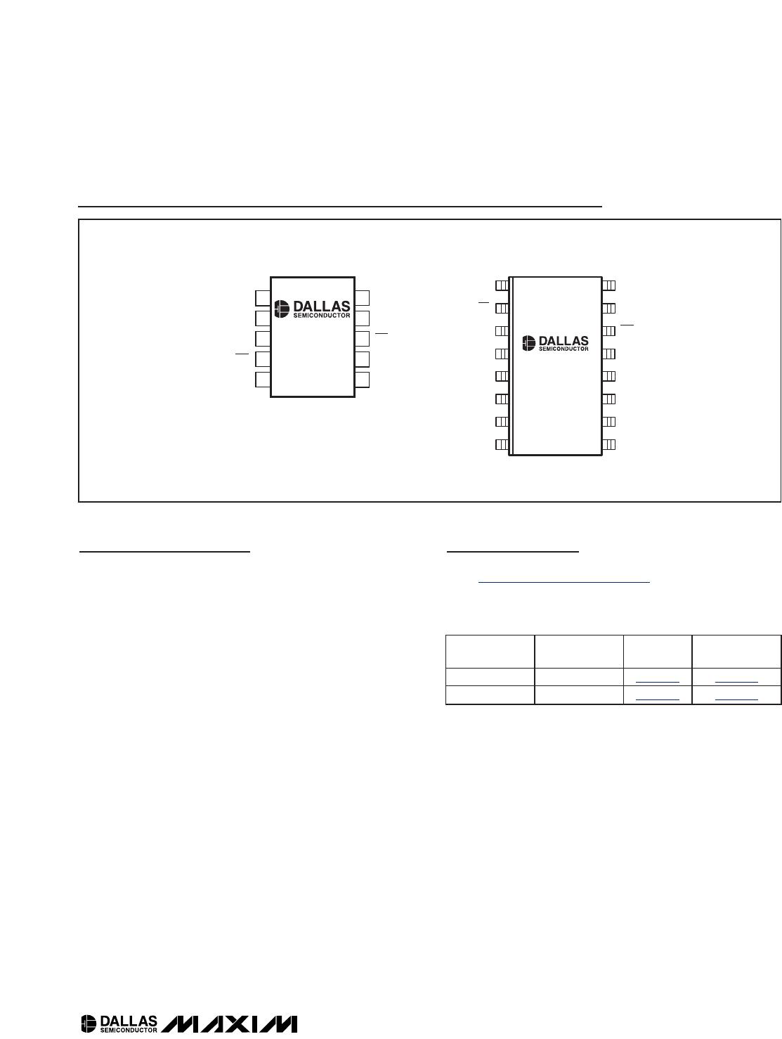
I
2
C, 32-Bit Binary Counter Watchdog RTC with
Trickle Charger and Reset Input/Output
16 ____________________________________________________________________