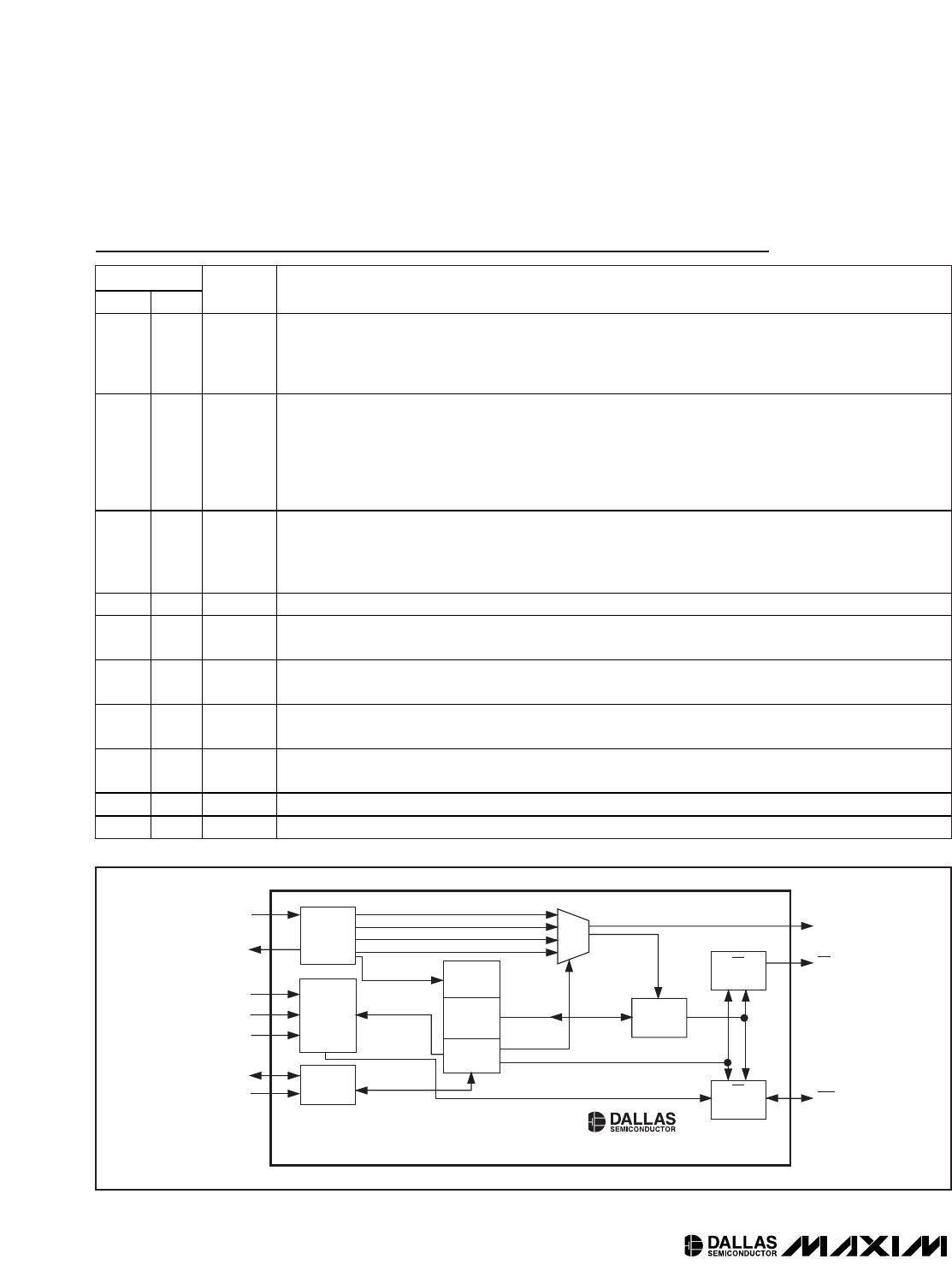
Detailed Description
The DS1374 is a real-time clock with an I
2
C serial inter-
face. It provides elapsed seconds from a user-defined
starting point in a 32-bit counter (Figure 4). A 24-bit
counter can be configured as either a watchdog
counter or an alarm counter. An on-chip oscillator cir-
cuit uses a customer-supplied 32.768kHz crystal to
keep time. A power-control circuit switches operation
from V
CC
to V
BACKUP
and back when power on V
CC
is
cycled. The oscillator and counters continue to operate
when powered by either supply. If a rechargeable
backup supply is used, a trickle charger can be
enabled to charge the backup supply while V
CC
is on.
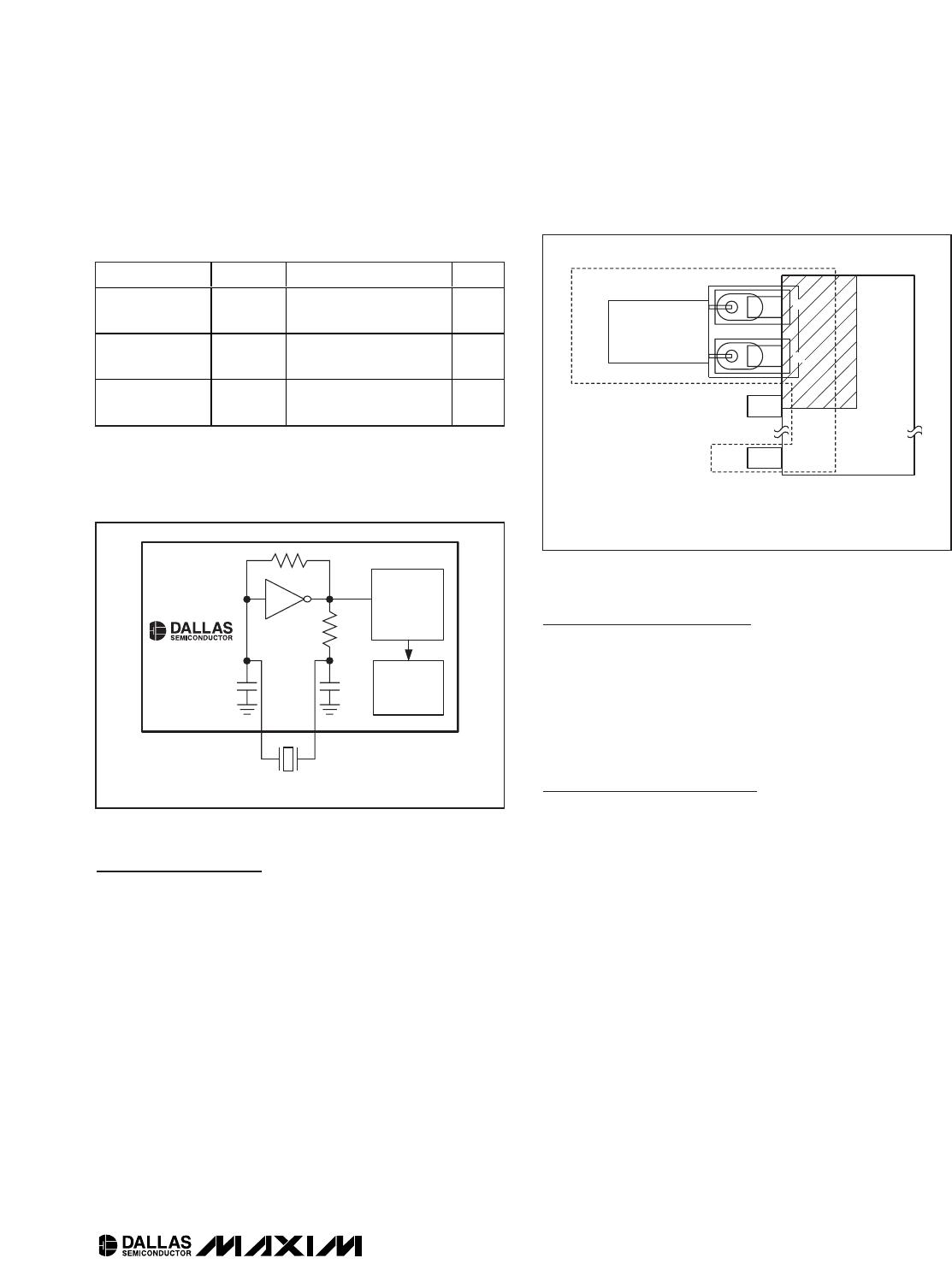
Oscillator Circuit
The DS1374 uses an external 32.768kHz crystal. The
oscillator circuit does not require any external resistors
or capacitors to operate. Table 1 specifies several crys-
tal parameters for the external crystal. Figure 5 shows a
functional schematic of the oscillator circuit. The startup
time is usually less than 1 second when using a crystal
with the specified characteristics.
Clock Accuracy
Clock accuracy is dependent upon the accuracy of the
crystal and the accuracy of the match between the
capacitive load of the oscillator circuit and the capacitive
load for which the crystal was trimmed. Additional error
is added by crystal frequency drift caused by tempera-
ture shifts. External circuit noise coupled into the oscilla-
tor circuit can result in the clock running fast. Figure 6
shows a typical PC board layout for isolating the crystal
and oscillator from noise. Refer to
Application Note 58:
Crystal Considerations with Dallas Real-Time Clocks
for
detailed information.
DS1374C Only
The DS1374C integrates a standard 32,768Hz crystal
into the package. Typical accuracy at nominal V
CC
and
25°C is approximately 10ppm. See
Application Note 58
for information about crystal accuracy vs. temperature.
DS1374
I
2
C, 32-Bit Binary Counter Watchdog RTC with
Trickle Charger and Reset Input/Output
_____________________________________________________________________ 9
SIGNAL LINE AND THE PACKAGE.