Expand menu
Hello, Sign in
My Account
0
Cart
Home
Products
Sensors
Semiconductors
Passive Components
Connectors
Power
Electromechanical
Optoelectronics
Circuit Protection
Integrated Circuits - ICs
Main Products
Manufacturers
Blog
Services
About OMO
About Us
Contact Us
Check Stock
AD9201ARSZ
P1-P3
P4-P6
P7-P9
P10-P12
P13-P15
P16-P18
P19-P21
AD9201
–15–
REV. D
SYNTHESIZER
20MHz
2Vp-p
+5V
DSP
EQUIPMENT
ANTI-
ALIAS
FILTER
+3V
+3V
SYNTHESIZER
1MHz
1Vp-p
AGND
AVDD
DGND1
DVDD
DGND2
DRVDD
P1
CLOCK
Q IN
AD9201
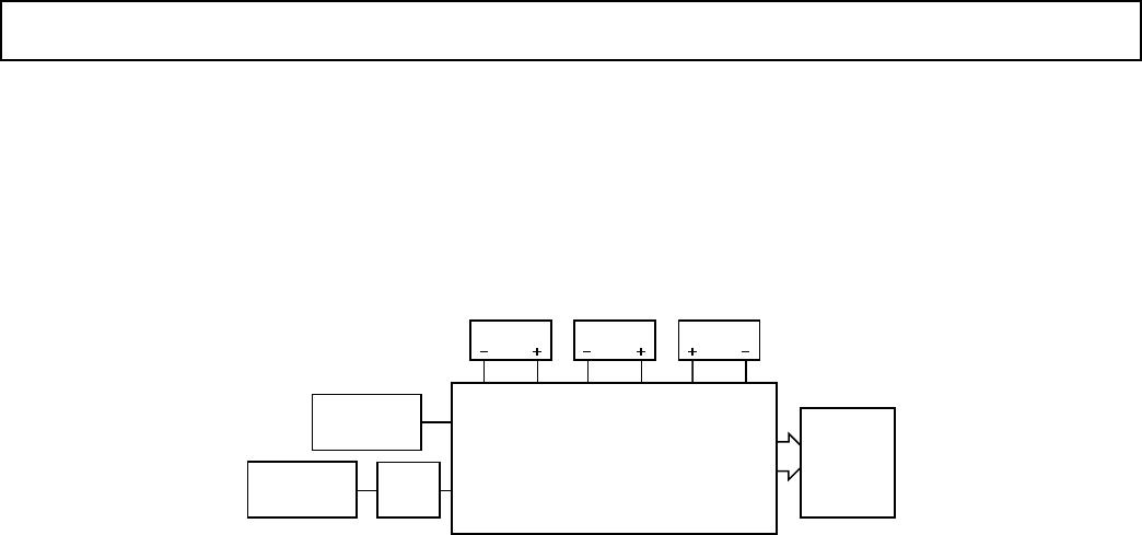
Figure 35.
Evaluation Board Connections
EVALUATION BOARD
The AD9201 evaluation board is shipped “ready to run.”
Power and signal generators should be connected as shown in
Figure 35. Then the user can observe the performance of the Q
channel. If the user wants to observe the I channel, then he
should install a jumper at JP22 Pins 1 and 2. If the user wants to
toggle
between I and Q channels, then a CMOS level pulse train
should be
applied to the “strobe” jack after appropriate jumper
connections.
AD9201
–16–
REV. D
– 9201EB –
R50
R51
C14
C24
R52
R53
C20
C22
C50
C51
C29
C52
C53
C14
C17
C23
C27
+C5
+C36
C35
C55
C4
C54
(NOT TO SCALE)
REV
Figure 36.
Evaluation Board Solder-Side Silkscreen
(NOT TO SCALE)
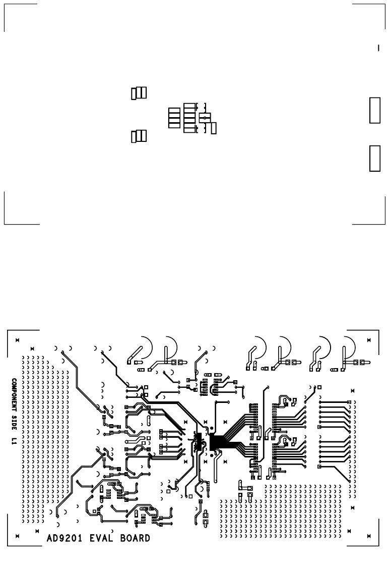
Figure 37.
Evaluation Board Component-Side Layout
AD9201
–17–
REV. D
(NOT TO SCALE)
Figure 38.
Evaluation Board Ground Plane Layout
(NOT TO SCALE)
Figure 39.
Evaluation Board Solder-Side Layout
P1-P3
P4-P6
P7-P9
P10-P12
P13-P15
P16-P18
P19-P21
AD9201ARSZ
Mfr. #:
Buy AD9201ARSZ
Manufacturer:
Analog Devices Inc.
Description:
Analog to Digital Converters - ADC Dual CH 20MHz 10B Resolution CMOS
Lifecycle:
New from this manufacturer.
Delivery:
DHL
FedEx
Ups
TNT
EMS
Payment:
T/T
Paypal
Visa
MoneyGram
Western
Union
Products related to this Datasheet
AD9201ARSZRL
AD9201ARSZ
AD9201ARS
AD9201ARSRL