MAX2361/MAX2363/MAX2365
Complete Dual-Band
Quadrature Transmitters
16 ______________________________________________________________________________________
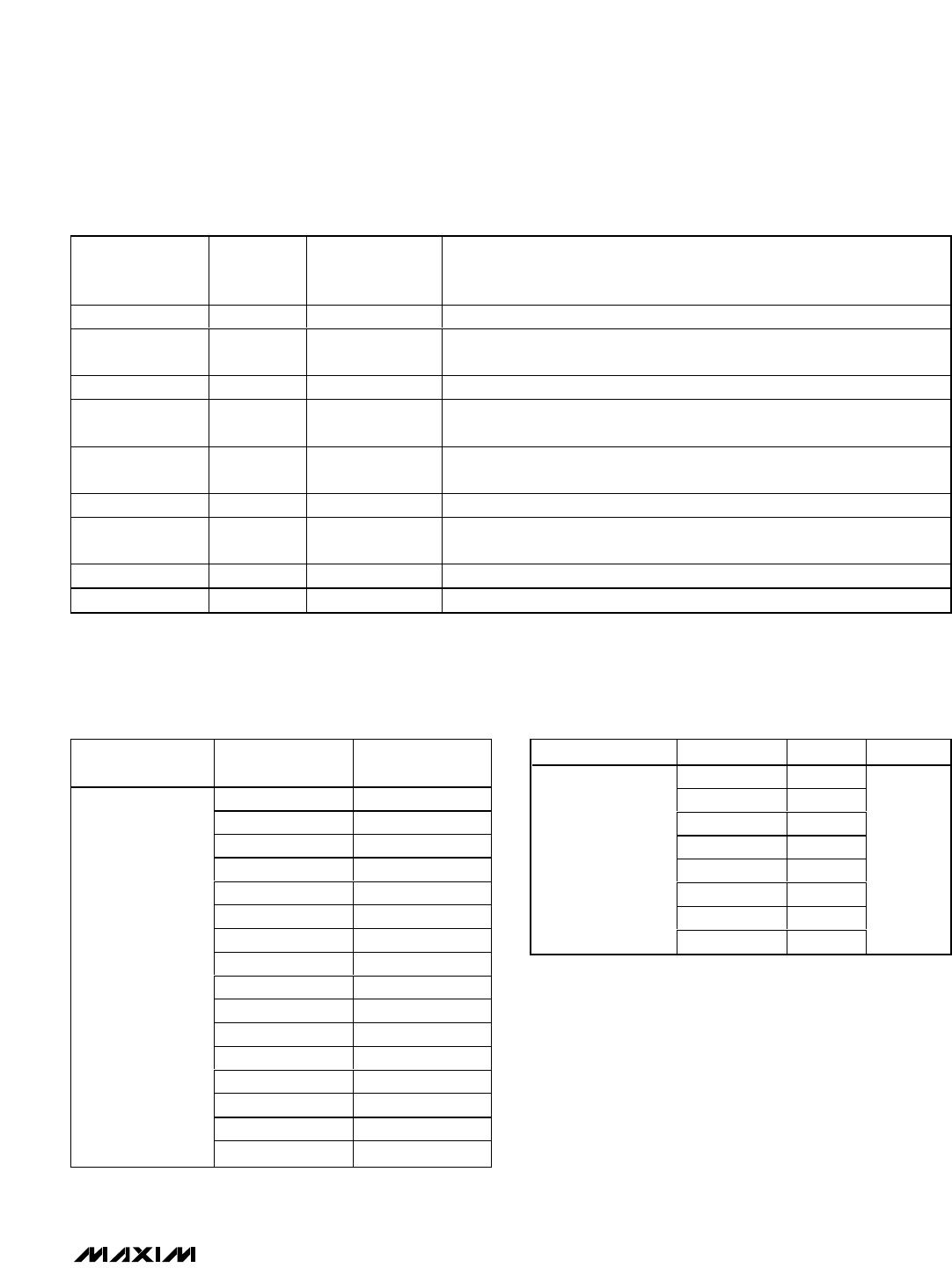
Table 3. Configuration Register (CONFIG)
BIT
LOCATION
(0 = LSB)
POWER-UP
STATE
Determines output mode for LOCK detector pin as follows:
00 = test mode, LD_MODE cannot be 00 for normal operation
01 = IF PLL lock detector
10 = RF PLL lock detector
11 = logical AND of IF PLL and RF PLL lock detectors
1, 011LD_MODE
Works in conjunction with RCP_TURBO1 (OPCTRL register) to set the turbo-
charge current mode. (See Table 7).
21RCP_TURBO2
1 activates turbocharge feature, providing an additional IF charge-pump cur-
rent during frequency acquisition.
31
IF_TURBO_
CHARGE
RF phase-detector polarity; 1 selects positive polarity (increasing tuning voltage
on the VCO produces increasing frequency); 0 selects negative polarity
(increasing voltage on the VCO produces decreasing frequency).
41RF_PD_POL
IF phase-detector polarity; 1 selects positive polarity (increasing tuning voltage
on the VCO produces increasing frequency); 0 selects negative polarity
(increasing tuning voltage on the VCO produces decreasing frequency).
51IF_PD_POL
7, 6
12
11
10
9, 8
13
14
15
A 2-bit register sets the RF charge-pump current as follows:
00 = 325µA
01 = 650µA
10 = 738µA
11 = 1063µA
00RCP
1 selects 200mV
RMS
input mode; 0 selects 100mV
RMS
input mode.1IQ_LEVEL
1 selects ÷2 on IFLO port; 0 bypasses the divider.0BUF_DIV
1 bypasses IF VCO and enables a buffered input for external VCO use.0VCO_BYPASS
A 2-bit register sets the IF charge-pump current as follows:
00 = 139µA
01 = 192µA
10 = 278µA
11 = 390µA
00ICP
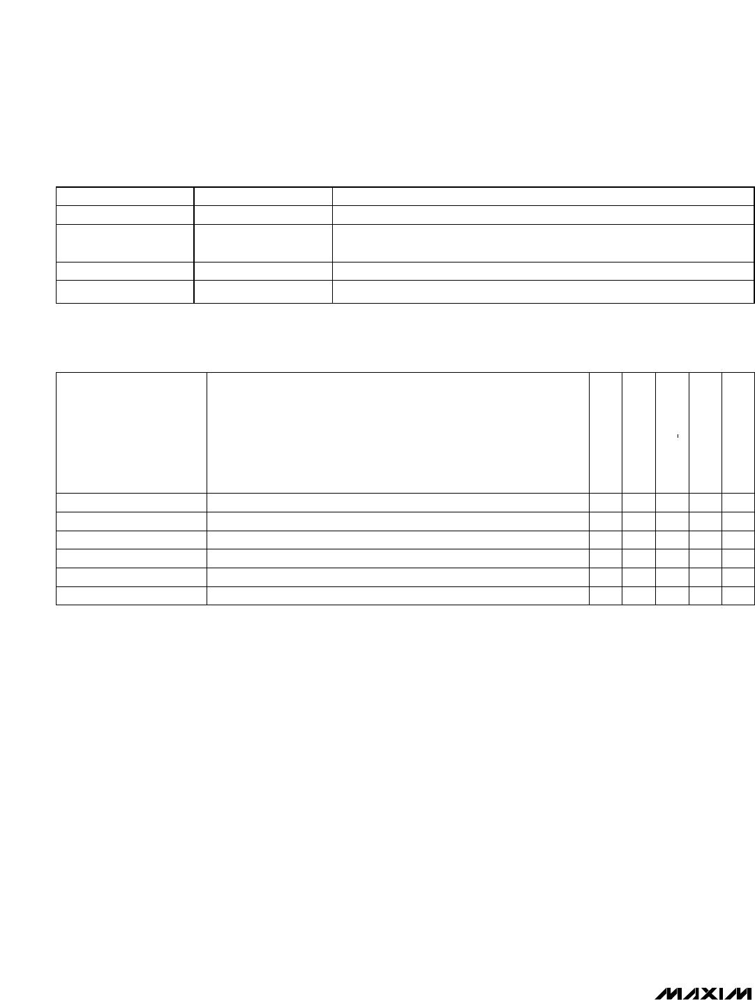
0 for normal operation, 1 turns off the bias current to RFH0 output driver.0ZERO_BIAS
0 shuts down the RF PLL. This mode is used with an external RF PLL.1
RF_PLL_
SHDN
0 shuts down the IF PLL. This mode is used with an external IF PLL.1IF_PLL_SHDN
FUNCTIONBIT NAME