PCA9505_9506 All information provided in this document is subject to legal disclaimers. © NXP B.V. 2010. All rights reserved.
Product data sheet Rev. 4 — 3 August 2010 7 of 34
NXP Semiconductors
PCA9505/06
40-bit I
2
C-bus I/O port with RESET, OE and INT
[1] HVQFN56 package die supply ground is connected to both V
SS
pins and exposed center pad. V
SS
pins
must be connected to supply ground for proper device operation. For enhanced thermal, electrical, and
board level performance, the exposed pad needs to be soldered to the board using a corresponding
thermal pad on the board and for proper heat conduction through the board, thermal vias need to be
incorporated in the printed-circuit board in the thermal pad region.
7. Functional description
Refer to Figure 1 “Block diagram of PCA9505/06 and Figure 2 “Simplified schematic of
IO0_0 to IO4_7.
7.1 Device address
Following a START condition, the bus master must send the address of the slave it is
accessing and the operation it wants to perform (read or write). The address of the
PCA9505/06 is shown in Figure 5
. Slave address pins A2, A1, and A0 choose 1 of 8 slave
addresses and need to be connected to V
DD
(1) or V
SS
(0). To conserve power, no internal
pull-up resistors are incorporated on A2, A1, and A0.
The last bit of the first byte defines the operation to be performed. When set to logic 1 a
read is selected, while a logic 0 selects a write operation.
7.2 Command register
Following the successful acknowledgement of the slave address + R/W bit, the bus
master will send a byte to the PCA9505/06, which will be stored in the Command register.
OE 30 23 I active LOW output enable input
INT
55 48 O active LOW interrupt output
RESET
56 49 I active LOW reset input
Table 2. Pin description
…continued
Symbol Pin Type Description
TSSOP56 HVQFN56
Fig 5. PCA9505/06 address
002aab49
4
0 1 0 0 A2 A1 A0 R/W
fixed
slave address
programmable
Fig 6. Command register
002aab495
1 0 0 0 0 0 0 0
AI D5 D4 D3 D2 D1 D0
Auto-Increment
register number
default at power-up
or after RESET
PCA9505_9506 All information provided in this document is subject to legal disclaimers. © NXP B.V. 2010. All rights reserved.
Product data sheet Rev. 4 — 3 August 2010 8 of 34
NXP Semiconductors
PCA9505/06
40-bit I
2
C-bus I/O port with RESET, OE and INT
The lowest 6 bits are used as a pointer to determine which register will be accessed. The
registers are:
IP: Input Port registers (5 registers)
OP: Output Port registers (5 registers)
PI: Polarity Inversion registers (5 registers)
IOC: I/O Configuration registers (5 registers)
MSK: Mask interrupt registers (5 registers)
If the Auto-Increment flag is set (AI = 1), the 3 least significant bits are automatically
incremented after a read or write. This allows the user to program and/or read the
5 register banks sequentially.
If more than 5 bytes of data are written and AI = 1, previous data in the selected registers
will be overwritten. Reserved registers are skipped and not accessed (refer to Table 3
).
If the Auto-Increment flag is cleared (AI = 0), the 3 least significant bits are not
incremented after data is read or written. During a read operation, the same register bank
is read each time. During a write operation, data is written to the same register bank each
time.
Only a Command register code with the 5 least significant bits equal to the 25 allowable
values as defined in Table 3
are valid. Reserved or undefined command codes must not
be accessed for proper device functionality. At power-up, this register defaults to 0x80,
with the AI bit set to logic 1, and the lowest 7 bits set to logic 0.
During a write operation, the PCA9505/06 will acknowledge a byte sent to OPx, PIx, and
IOCx and MSKx registers, but will not acknowledge a byte sent to the IPx registers since
these are read-only registers.
PCA9505_9506 All information provided in this document is subject to legal disclaimers. © NXP B.V. 2010. All rights reserved.
Product data sheet Rev. 4 — 3 August 2010 9 of 34
NXP Semiconductors
PCA9505/06
40-bit I
2
C-bus I/O port with RESET, OE and INT
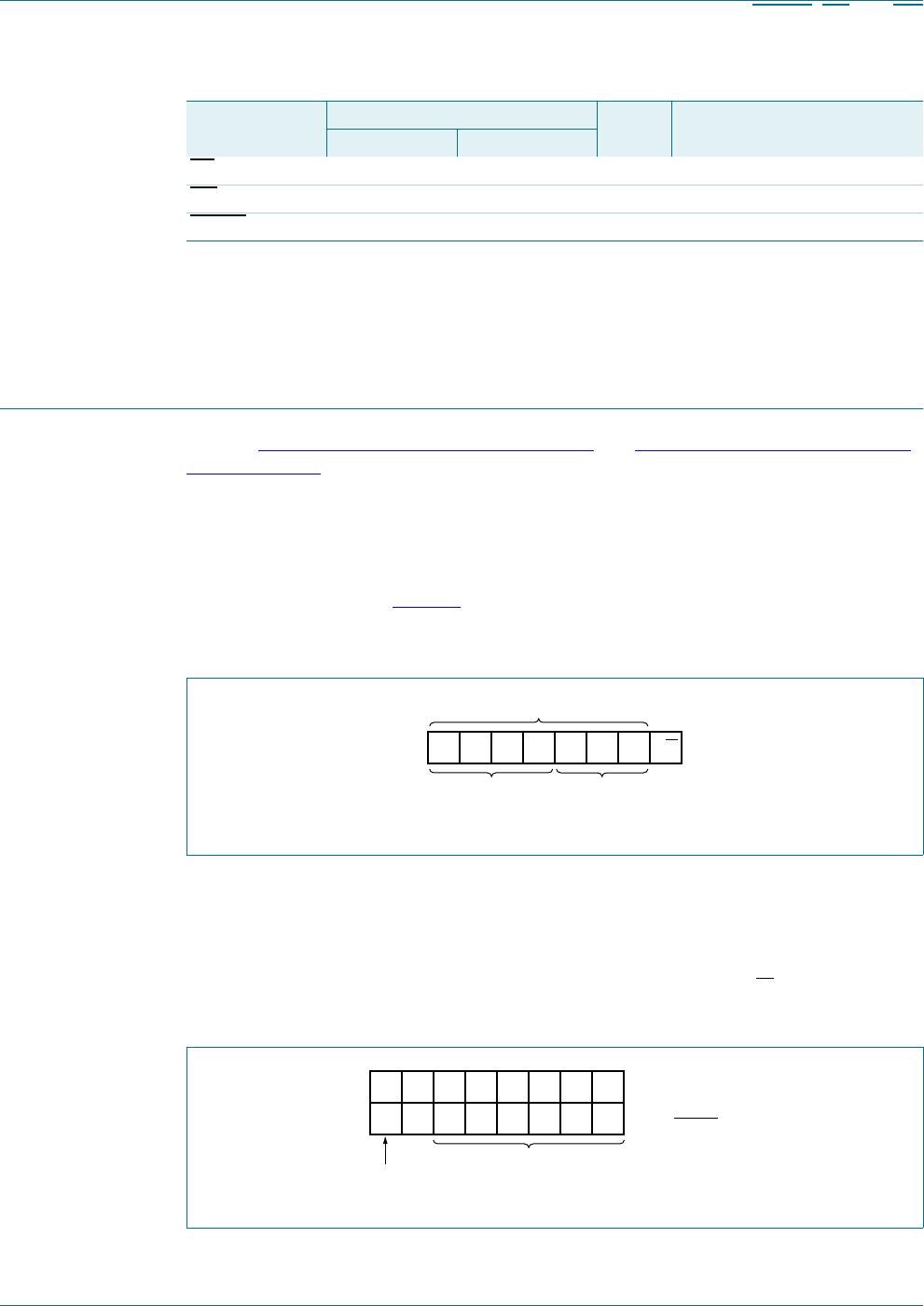
7.3 Register definitions
Table 3. Register summary
Register #
(hex)
D5 D4 D3 D2 D1 D0 Symbol Access Description
Input Port registers
00 000000IP0 read only Input Port register bank 0
01 000001IP1 read only Input Port register bank 1
02 000010IP2 read only Input Port register bank 2
03 000011IP3 read only Input Port register bank 3
04 000100IP4 read only Input Port register bank 4
05 000101- - reserved for future use
06 000110- - reserved for future use
07 000111- - reserved for future use
Output Port registers
08 001000OP0 read/writeOutput Port register bank 0
09 001001OP1 read/writeOutput Port register bank 1
0A 001010OP2 read/writeOutput Port register bank 2
0B 001011OP3 read/writeOutput Port register bank 3
0C 001100OP4 read/writeOutput Port register bank 4
0D 001101- - reserved for future use
0E 001110- - reserved for future use
0F 001111- - reserved for future use
Polarity Inversion registers
10 010000PI0 read/writePolarity Inversion register bank 0
11 010001PI1 read/writePolarity Inversion register bank 1
12 010010PI2 read/writePolarity Inversion register bank 2
13 010011PI3 read/writePolarity Inversion register bank 3
14 010100PI4 read/writePolarity Inversion register bank 4
15 010101- - reserved for future use
16 010110- - reserved for future use
17 010111- - reserved for future use
I/O Configuration registers
18 011000IOC0 read/writeI/O Configuration register bank 0
19 011001IOC1 read/writeI/O Configuration register bank 1
1A 011010IOC2 read/writeI/O Configuration register bank 2
1B 011011IOC3 read/writeI/O Configuration register bank 3
1C 011100IOC4 read/writeI/O Configuration register bank 4
1D 011101- - reserved for future use
1E 011110- - reserved for future use
1F 011111- - reserved for future use

PCA9506BS,118

Mfr. #:
Manufacturer:
NXP Semiconductors
Description:
Interface - I/O Expanders I/O EXPANDER I2C
Lifecycle:
New from this manufacturer.
Delivery:
DHL FedEx Ups TNT EMS
Payment:
T/T Paypal Visa MoneyGram Western Union