LT3757/LT3757A
23
3757afd
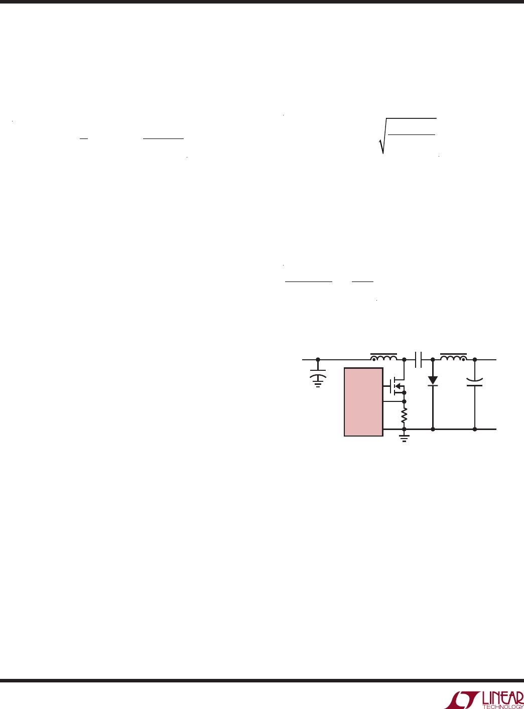
Given an operating input voltage range, and having chosen
the operating frequency and ripple current in the inductor,
the inductor value (L1 and L2 are independent) of the SEPIC
converter can be determined using the following equation:
L1= L2 =
V
IN(MIN)
0.5 • ∆I
SW
• f
• D
MAX
For most SEPIC applications, the equal inductor values
will fall in the range of 1µH to 100µH.
By making L1 = L2, and winding them on the same core, the
value of inductance in the preceding equation is replaced
by 2L, due to mutual inductance:
L =
V
IN(MIN)
∆I
SW
• f
• D
MAX
This maintains the same ripple current and energy storage
in the inductors. The peak inductor currents are:
I
L1(PEAK)
= I
L1(MAX)
+ 0.5 • ∆I
L1
I
L2(PEAK)
= I
L2(MAX)
+ 0.5 • ∆I
L2
The RMS inductor currents are:
I
L1(RMS)
=I
L1(MAX)
• 1+
c
2
L1
12
where:
c
L1
=
∆I
L1
I
L1(MAX)
I
L2(RMS)
=I
L2(MAX)
• 1+
c
2
L2
12
where:
c
L2
=
∆I
L2
I
L2 (MAX)
Based on the preceding equations, the user should choose
the inductors having sufficient saturation and RMS cur-
rent ratings.
In a SEPIC converter, when the power switch is turned on,
the current flowing through the sense resistor (I
SENSE
) is
the switch current.
Set the sense voltage at I
SENSE(PEAK)
to be the minimum
of the SENSE current limit threshold with a 20% margin.
The sense resistor value can then be calculated to be:
R
SENSE
=
80 mV
I
SW(PEAK)
SEPIC Converter: Power MOSFET Selection
For the SEPIC configuration, choose a MOSFET with a
V
DC
rating higher than the sum of the output voltage and
input voltage by a safety margin (a 10V safety margin is
usually sufficient).
The power dissipated by the MOSFET in a SEPIC con-
verter is:
P
FET
= I
2
SW(MAX)
• R
DS(ON)
• D
MAX
+ 2 • (V
IN(MIN)
+ V
OUT
)
2
• I
L(MAX)
• C
RSS
• f /1A
The first term in this equation represents the conduction
losses in the device, and the second term, the switching
loss. C
RSS
is the reverse transfer capacitance, which is
usually specified in the MOSFET characteristics.
For maximum efficiency, R
DS(ON)
and C
RSS
should be
minimized. From a known power dissipated in the power
MOSFET, its junction temperature can be obtained using
the following equation:
T
J
= T
A
+ P
FET
• θ
JA
= T
A
+ P
FET
• (θ
JC
+ θ
CA
)
T
J
must not exceed the MOSFET maximum junction
temperature rating. It is recommended to measure the
MOSFET temperature in steady state to ensure that absolute
maximum ratings are not exceeded.
applicaTions inForMaTion