CYRF89135
Document Number: 001-86331 Rev. ** Page 16 of 41
DC GPIO Specifications
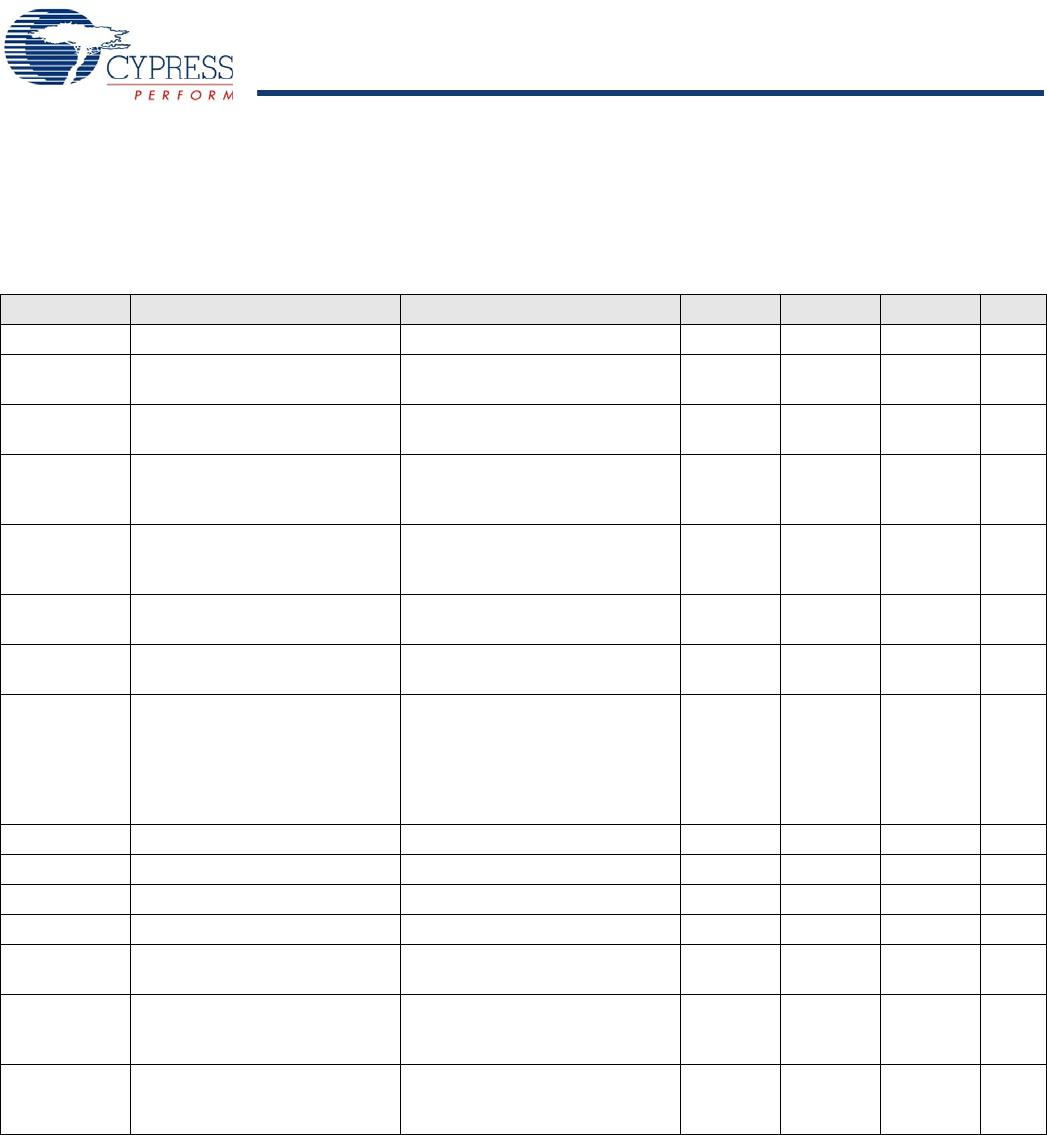
The following tables list guaranteed maximum and minimum specifications for the voltage and temperature ranges: 2.4 V to 3.0 V and
0 °C
T
A
70 °C, or 1.9 V to 2.4 V and 0 °C T
A
°C, respectively. Typical parameters apply to 3.3 V at 25 °C and are for design
guidance only.
Table 5. 2.4 V to 3.0 V DC GPIO Specifications
Symbol Description Conditions Min Typ Max Units
R
PU
Pull-up resistor 4 5.60 8 k
V
OH1
High output voltage Port 2 or 3 or
4 pins
I
OH
< 10 A, maximum of 10 mA
source current in all I/Os
V
IN
– 0.20 V
V
OH2
High output voltage Port 2 or 3 or
4 pins
I
OH
= 0.2 mA, maximum of 10 mA
source current in all I/Os
V
IN
– 0.40 V
V
OH3
High output voltage Port 0 or 1
pins with LDO regulator Disabled
for port 1
I
OH
< 10 A, maximum of 10 mA
source current in all I/Os
V
IN
– 0.20 V
V
OH4
High output voltage Port 0 or 1
pins with LDO regulator Disabled
for Port 1
I
OH
= 2 mA, maximum of 10 mA
source current in all I/Os
V
IN
– 0.50 V
V
OH5A
High output voltage Port 1 pins
with LDO enabled for 1.8 V out
I
OH
< 10 A, V
IN
> 2.4 V, maximum
of 20 mA source current in all I/Os
1.50 1.80 2.10 V
V
OH6A
High output voltage Port 1 pins
with LDO enabled for 1.8 V out
I
OH
= 1 mA, V
IN
> 2.4 V, maximum
of 20 mA source current in all I/Os
1.20 V
V
OL
Low output voltage IOL = 10 mA, maximum of 30 mA
sink current on even port pins (for
example, P0[2] and P1[4]) and
30 mA sink current on odd port
pins (for example, P0[3] and
P1[5])
––0.75V
V
IL
Input low voltage 0.72 V
V
IH
Input high voltage 1.40 V
V
H
Input hysteresis voltage 80 mV
I
IL
Input leakage (absolute value) 1 1000 nA
C
PIN
Capacitive load on pins Package and pin dependent
Temp = 25
C
0.50
1.70 7 pF
V
ILLVT2.5
Input Low Voltage with low
threshold enable set, Enable for
Port1
Bit3 of IO_CFG1 set to enable low
threshold voltage of Port1 input
0.7 V
V
IHLVT2.5
Input High Voltage with low
threshold enable set, Enable for
Port1
Bit3 of IO_CFG1 set to enable low
threshold voltage of Port1 input
1.2 V
CYRF89135
Document Number: 001-86331 Rev. ** Page 17 of 41
Table 6. 1.9 V to 2.4 V DC GPIO Specifications
Symbol Description Conditions Min Typ Max Units
R
PU
Pull-up resistor 4 5.60 8 k
V
OH1
High output voltage Port 2 or 3 or
4 pins
I
OH
= 10 A, maximum of 10 mA
source current in all I/Os
V
IN
– 0.20 V
V
OH2
High output voltage Port 2 or 3 or
4 pins
I
OH
= 0.5 mA, maximum of 10 mA
source current in all I/Os
V
IN
– 0.50 V
V
OH3
High output voltage Port 0 or 1
pins with LDO regulator Disabled
for Port 1
I
OH
= 100 A, maximum of 10 mA
source current in all I/Os
V
IN
– 0.20 V
V
OH4
High output voltage Port 0 or 1
Pins with LDO Regulator
Disabled for Port 1
I
OH
= 2 mA, maximum of 10 mA
source current in all I/Os
V
IN
– 0.50 V
V
OL
Low output voltage I
OL
= 5 mA, maximum of 20 mA
sink current on even port pins (for
example, P0[2] and P1[4]) and
30 mA sink current on odd port
pins (for example, P0[3] and
P1[5])
––0.40V
V
IL
Input low voltage 0.30 × V
IN
V
V
IH
Input high voltage 0.65 × V
IN
––V
V
H
Input hysteresis voltage 80 mV
I
IL
Input leakage (absolute value) 1 1000 nA
C
PIN
Capacitive load on pins Package and pin dependent
temp = 25 °C
0.50 1.70 7 pF
CYRF89135
Document Number: 001-86331 Rev. ** Page 18 of 41
Analog DC Mux Bus Specifications
The following table lists guaranteed maximum and minimum specifications for the entire voltage and temperature ranges.
DC Low Power Comparator Specifications
The following table lists guaranteed maximum and minimum specifications for the entire voltage and temperature ranges.
Comparator User Module Electrical Specifications
The following table lists the guaranteed maximum and minimum specifications. Unless stated otherwise, the specifications are for the
entire device voltage and temperature operating range: 0 °C
T
A
70 °C, 1.9 V V
IN
3.6 V.
Table 7. DC Analog Mux Bus Specifications
Symbol Description Conditions Min Typ Max Units
R
SW
Switch resistance to common
analog bus
800
R
GND
Resistance of initialization switch
to GND
800
The maximum pin voltage for measuring R
SW
and R
GND
is 1.8 V.
Table 8. DC Comparator Specifications
Symbol Description Conditions Min Typ Max Units
V
LPC
Low power comparator (LPC)
common mode
Maximum voltage limited to V
IN
0.0–1.8V
I
LPC
LPC supply current 10 40 A
V
OSLPC
LPC voltage offset 3 30 mV
Table 9. Comparator User Module Electrical Specifications
Symbol Description Conditions Min Typ Max Units
t
COMP
Comparator response time 50 mV overdrive 70 100 ns
Offset Valid from 0.2 V to (V
IN
– 0.2 V) 2.5 30 mV
Current Average DC current, 50 mV
overdrive
20 80 µA
PSRR
Supply voltage > 2 V Power supply rejection ratio 80 dB
Supply voltage < 2 V Power supply rejection ratio 40 dB
Input range 0 1.5 V

CYRF89135-68LTXC

Mfr. #:
Manufacturer:
Cypress Semiconductor
Description:
RF Transceiver Wireless Capacitive Touch
Lifecycle:
New from this manufacturer.
Delivery:
DHL FedEx Ups TNT EMS
Payment:
T/T Paypal Visa MoneyGram Western Union

Products related to this Datasheet