Document Number: 001-65659 Rev. *I Page 10 of 26
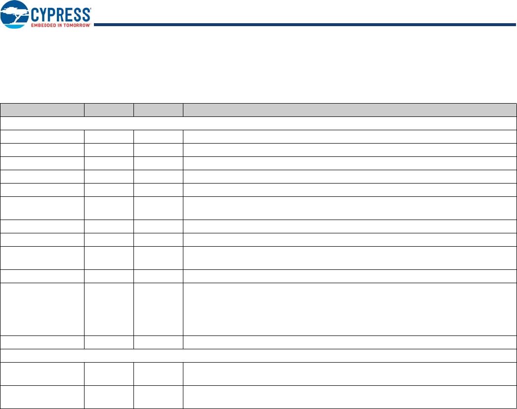
Downstream Port 1
DD–[1] 5 I/O/Z Downstream D– Signal.
DD+[1] 6 I/O/Z Downstream D+ Signal.
AMBER[1]
SPI_CS
46 O(R
DN
)
O(R
DN
)
LED. Driver output for amber LED. port indicator support.
SPI_CS. Can be used as chip select to access external SPI EEPROM.
GREEN[1]
[2]
SPI_SK
FIXED_PORT1
45 O(R
DN
)
O(R
DN
)
I(R
DN
)
LED. Driver output for green LED. Port indicator support.
SPI_SK. Can be used as SPI Clock to access external SPI EEPROM.
FIXED_PORT1. At POR used to set Port1 as non removable port. Refer Pin
Configuration Options on page 15.
OVR#[1] 42 I(R
UP
) Overcurrent Condition Detection Input. Active LOW Overcurrent Condition
Detection Input.
PWR#[1]
I
2
C_SDA
43 O/Z
I/O
Power Switch Driver Output. Default is Active LOW.
I
2
C_SDA. Can be used as I
2
C Data pin, connected with I
2
C EEPROM.
Downstream Port 2
DD–[2] 9 I/O/Z Downstream D– Signal.
DD+[2] 10 I/O/Z Downstream D+ Signal.
AMBER[2]
SPI_MOSI
PWR_PIN_POL
36 O(R
DN
)
O(R
DN
)
I(R
DN
)
LED. Driver output for Amber LED. Port Indicator Support.
SPI_MOSI. Can be used as Data Out to access external SPI EEPROM.
PWR_PIN_POL. Used for power switch enable pin polarity setting. Refer Pin
Configuration Options on page 15.
GREEN[2]
[2]
SPI_MISO
FIXED_PORT2
35 O(R
DN
)
I(R
DN
)
I(R
DN
)
LED. Driver output for Green LED. Port Indicator Support.
SPI_MISO. Can be used as Data In to access external SPI EEPROM.
FIXED_PORT2. At POR used to set Port2 as non removable port. Refer Pin
Configuration Options on page 15.
OVR#[2] 40 I(R
UP
) Overcurrent Condition Detection Input. Active LOW Overcurrent Condition
Detection Input.
PWR#[2] 41 O/Z Power Switch Driver Output. Default is Active LOW
Downstream Port 3
DD–[3] 17 I/O/Z Downstream D– Signal.
DD+[3] 18 I/O/Z Downstream D+ Signal.
AMBER[3]
SET_PORT_NUM2
33 O(R
DN
)
I(R
DN
)
LED. Driver output for Amber LED. Port indicator support.
SET_PORT_NUM2. Used to set port numbering along with SET_PORT_NUM1.
Refer Pin Configuration Options on page 15.
GREEN[3]
FIXED_PORT3
32 O(R
DN
)
I(R
DN
)
LED. Driver output for Green LED. Port indicator support.
FIXED_PORT3. At POR used to set Port3 as non removable port. Refer Pin
Configuration Options on page 15.
OVR#[3] 30 I(R
UP
) Overcurrent Condition Detection Input. Active LOW Overcurrent Condition
Detection Input.
PWR#[3] 31 O/Z Power Switch Driver Output. Default is Active LOW.
Pin Definitions (continued)
48-pin TQFP Package
Pin Name Pin No. Type
[1]
Description
Note
2. Pin-strapping GREEN[1] and GREEN[2] enables proprietary function that may affect the normal functionality of HX2VL. Configuring Port #1 and #2 as non-removable
by pin-strapping should be avoided.