Document Number: 001-65659 Rev. *I Page 4 of 26
CY7C65642
Introduction
HX2VL is Cypress’s next generation family of high- performance,
very low-power USB 2.0 hub controllers. HX2VL has integrated
upstream and downstream transceivers; a USB serial interface
engine (SIE); USB hub control and repeater logic; and
transaction translator (TT) logic. Cypress has also integrated
external components such as voltage regulator and
pull-up/pull-down resistors, reducing the overall BOM required to
implement a USB hub system.
The CY7C65642 is a part of the HX2VL portfolio with four
downstream ports and an independent TT dedicated for each
downstream port. This device option is for low-power but
high-performance applications that require up to four
downstream ports. The CY7C65642 is available in 48-pin TQFP
and 28-pin QFN package options.
All device options are supported by Cypress’s world class
reference design kits, which include board schematics, BOM,
Gerber files, Orcad files, and thorough design documentation.
HX2VL Architecture
The Block Diagram on page 1 shows the HX2VL TetraHub™
architecture.
USB Serial Interface Engine
The SIE allows HX2VL to communicate with the USB host. The
SIE handles the following USB activities independently of the
Hub Control Block.
Bit stuffing and unstuffing
Checksum generation and checking
TOKEN type identification
Address checking.
HS USB Control Logic
‘Hub Control’ block co-ordinates enumeration, suspend and
resume. It generates status and control signals for host access
to the hub. It also includes the frame timer that synchronizes the
hub to the host. It has status/control registers which function as
the interface to the firmware in the MCU.
Hub Repeater
The hub repeater manages the connectivity between upstream
and downstream facing ports that are operating at the same
speed. It supports full and high-speed connectivity. According to
the USB 2.0 specification, the hub repeater provides the
following functions:
Sets up and tears down connectivity on packet boundaries
Ensures orderly entry into and out of ‘Suspend’ state, including
proper handling of remote wakeups.
MCU
The HX2VL has MCU with 2 K ROM and 64 byte RAM. The MCU
operates with a 12 MHz clock to decode USB commands from
host and respond to the host. It can also handle GPIO settings
to provide higher flexibility to the customers and control the read
interface to the EEPROM which has extended configuration
options.
Transaction Translator
The TT translates data from one speed to another. A TT takes
high-speed split transactions and translates them to full or
low-speed transactions when the hub is operating at high-speed
(the upstream port is connected to a high speed host controller)
and has full or low- speed devices attached. The operating speed
of a device attached on a downstream port determines whether
the routing logic connects a port to the TT or to hub repeater.
When the upstream host and downstream device are functioning
at different speeds, the data is routed through the TT. In all other
cases, the data is routed through the repeater. For example, If a
full or low-speed device is connected to the high-speed host
upstream through the hub, then the data transfer route includes
TT. If a high-speed device is connected to the high-speed host
upstream through the hub, the transfer route includes the
repeater. When the hub is connected to a full-speed host
controller upstream, then high-speed peripheral does not
operate at its full capability. These devices only work at full
speed. Full and low-speed devices connected to this hub operate
at their normal speed.
Port Control
The downstream ‘Port Control’ block handles the
connect/disconnect and over current detection as well as the
power enable and LED control. It also generates the control
signals for the downstream transceivers.
Applications
Typical applications for the HX2VL device family are:
Docking stations
Standalone hubs
Monitor hubs
Multi-function printers
Digital televisions
Advanced port replicators
Keyboard hubs
Gaming consoles
Document Number: 001-65659 Rev. *I Page 5 of 26
CY7C65642
Functional Overview
The Cypress CY7C65642 USB 2.0 Hubs are low-power hub
solutions for USB which provide maximum transfer efficiency
with no TT multiplexing between downstream ports. The
CY7C65642 USB 2.0 Hubs integrate 1.5 k
upstream pull-up
resistors for full speed operation and all downstream 15 k
pull-down resistors and series termination resistors on all
upstream and downstream D+ and D– pins. This results in
optimization of system costs by providing built-in support for the
USB 2.0 specification.
System Initialization
On power up, CY7C65642 has an option to enumerate from the
default settings in the mask ROM or from reading an external
EEPROM for configuration information. At the most basic level,
this EEPROM has the Vendor ID (VID) and the Product ID (PID),
for the customer's application. For more specialized
applications, other configuration options can be specified. See
EEPROM Configuration Options on page 14 for more details.
CY7C65642 verifies the checksum before loading the EEPROM
contents as the descriptors.
Enumeration
CY7C65642 enables the pull-up resistor on D+ to indicate its
presence to the upstream hub, after which a USB Bus Reset is
expected. After a USB Bus Reset, CY7C65642 is in an
unaddressed, unconfigured state (configuration value set to’0’).
During the enumeration process, the host sets the hub's address
and configuration. After the hub is configured, the full hub
functionality is available.
Multiple Transaction Translator Support
After TetraHub is configured in a high speed system, it is in single
TT mode. The host may then set the hub into multiple TT mode
by sending a SetInterface command. In multiple TT mode, each
full speed port is handled independently and thus has a full
12 Mbps bandwidth available. In Single TT mode, all traffic from
the host destined for full or low-speed ports are forwarded to all
of those ports. This means that the 12 Mbps bandwidth is shared
by all full and low-speed ports.
Upstream Port
The upstream port includes the transmitter and the receiver state
machine. The transmitter and receiver operate in high speed and
full speed depending on the current hub configuration. The
transmitter state machine monitors the upstream facing port
while the Hub Repeater has connectivity in the upstream
direction. This machine prevents babble and disconnect events
on the downstream facing ports of this hub from propagating and
causing the hub to be disabled or disconnected by the hub to
which it is attached.
Downstream Ports
The CY7C65642 supports a maximum of four downstream ports,
each of which may be marked as usable or removable in the
EEPROM configuration, see EEPROM Configuration Options on
page 14. Additionally, it can also be configured by pin strapping,
see Pin Configuration Options on page 15.
Downstream D+ and D– pull-down resistors are incorporated in
CY7C65642 for each port. Before the hubs are configured, the
ports are driven Single Ended Zero, ((SE0) where both D+ and
D– are driven low) and are set to the unpowered state. When the
hub is configured, the ports are not driven and the host may
power the ports by sending a SetPortPower command for each
port. After a port is powered, any connect or disconnect event is
detected by the hub. Any change in the port state is reported by
the hubs back to the host through the Status Change Endpoint
(endpoint 1). On receipt of SetPortReset request for a port with
a device connected, the hub does as follows:
Performs a USB Reset on the corresponding port
Puts the port in an enabled state
Enables babble detection after the port is enabled.
Babble consists of a non idle condition on the port after EOF2. If
babble is detected on an enabled port, that port is disabled. A
ClearPortEnable request from the host also disables the
specified port.
Downstream ports can be individually suspended by the host
with the SetPortSuspend request. If the hub is not suspended, a
remote wakeup event on that port is reflected to the host through
a port change indication in the Hub Status Change Endpoint. If
the hub is suspended, a remote wakeup event on this port is
forwarded to the host. The host may resume the port by sending
a ClearPortSuspend command.
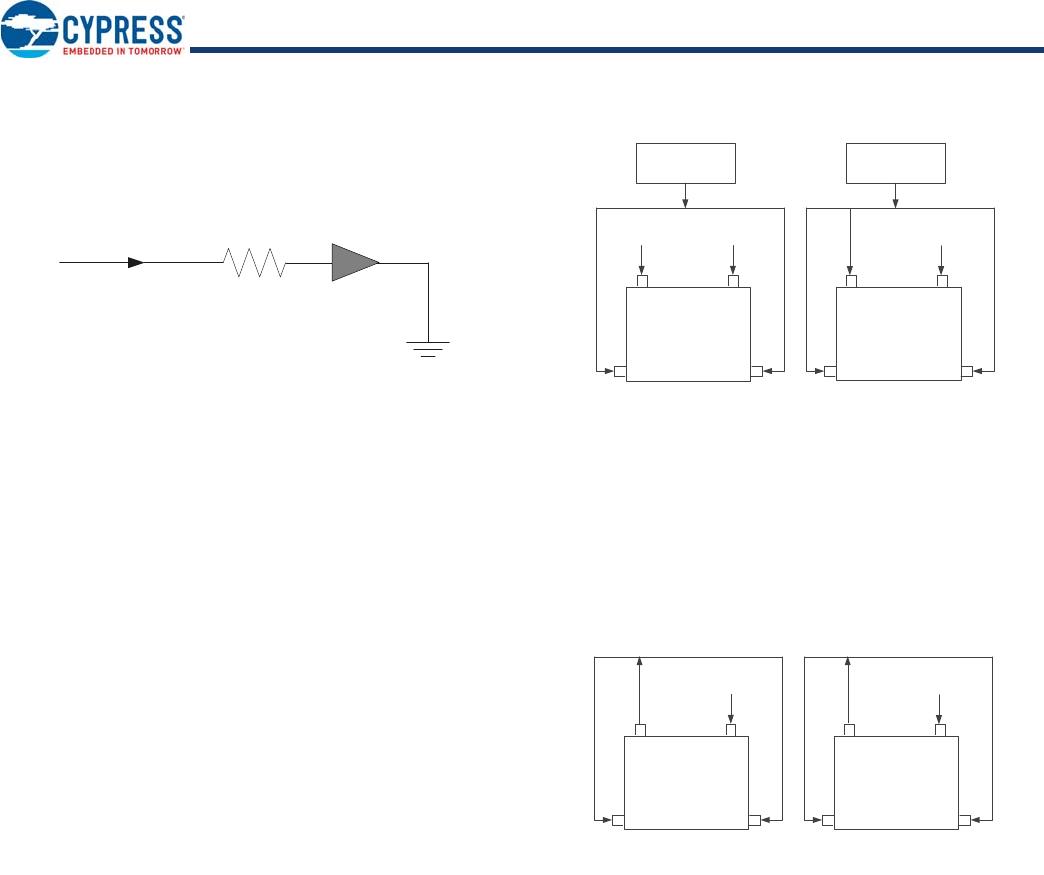
Power Switching
The CY7C65642 includes interface signals for external port
power switches. Both ganged and individual (per-port)
configurations are supported by pin strapping, see Pin
Configuration Options on page 15.
After enumerating, the host may power each port by sending a
SetPortPower request for that port. Power switching and
overcurrent detection are managed using respective control
signals (PWR#[n] and OVR#[n]) which are connected to an
external power switch device. Both High/Low enabled power
switches are supported and the polarity is configured through
GPIO setting, see Pin Configuration Options on page 15.
Overcurrent Detection
The OVR#[n] pins of the CY7C65642 series are connected to the
respective external power switch’s port overcurrent indication
(output) signals. After detecting an overcurrent condition, hub
reports overcurrent condition to the host and disables the
PWR#[n] output to the external power device. OVR#[n] has a
setup time of 20 ns. It takes 3 to 4 ms from overcurrent detection
to deassertion of PWR#[n]
Port Indicators
The USB 2.0 port indicators are also supported directly by
CY7C65642. According to the specification, each downstream
port of the hub optionally supports a status indicator. The
presence of indicators for downstream facing ports is specified
by bit 7 of the wHubCharacteristics field of the hub class
descriptor. The default CY7C65642 descriptor specifies that the
port indicators are supported. The CY7C65642 port indicators
has two modes of operation: automatic and manual.
Document Number: 001-65659 Rev. *I Page 6 of 26
CY7C65642
On power up the CY7C65642 defaults to automatic mode, where
the color of the Port Indicator (green, amber, off) indicates the
functional status of the CY7C65642 port. The LEDs are turned
off when the device is suspended.
Power Regulator
CY7C65642 requires 3.3 V source power for normal operation of
internal core logic and USB physical layer (PHY). The integrated
low-drop power regulator converts 5 V power input from USB
cable (Vbus) to 3.3 V source power. The 3.3 V power output is
guaranteed by an internal voltage reference circuit when the
input voltage is within the 4 V–5.5 V range. The regulator’s
maximum current loading is 150 mA, which provides tolerance
margin over CY7C65642’s normal power consumption of below
100 mA. The on chip regulator has a quiescent current of 28 µA.
External Regulation Scheme
CY7C65642 supports both external regulation and internal
regulation schemes. When an external regulation is chosen,
then for the 48-pin package, VCC and VREG are to be left open
with no connection. The external regulator output 3.3 V has to be
connected to VCC_A and VCC_D pins. This connection has to
be done externally, on board. For the 28-Pin package, the 3.3 V
output from the external regulator has to be connected to VREG,
VCC_A and VCC_D. The V
CC
pin has to be left open with no
connection. From the external input 3.3 V, 1.8 V is internally
generated for the chip’s internal usage.
Internal Regulation Scheme
When the built-in internal regulator is chosen, then the VCC pin
has to be connected to a 5 V, in both 48-pin and 28-pin packages.
Internally, the built-in regulator generates a 3.3 V and 1.8 V for
the chip’s internal usage. Also a 3.3 V output is available at
VREG pin, that has to be connected externally to VCC_A and
VCC_D.
Port Status
Indicator
LED
VCC_D
VCC
ExternalRegulationScheme
VCC_A
VREG
NC
NC
5Vto3.3V
Regulator
VCC_A VCC_D
VREG VCC
NC
CY7C65642
48Pin
CY7C65642
28Pin
5Vto3.3V
Regulator
3.3V
3.3V
VCC_D
VCC
InternalRegulationScheme
VCC_A
VREG
5V
VCC_A VCC_D
VREG VCC
5V
CY7C65642
48Pin
CY7C65642
28Pin

CY7C65642-28LTXC

Mfr. #:
Manufacturer:
Cypress Semiconductor
Description:
USB Interface IC TetraHub Ctrl USB2.0
Lifecycle:
New from this manufacturer.
Delivery:
DHL FedEx Ups TNT EMS
Payment:
T/T Paypal Visa MoneyGram Western Union