Document Number: 001-65659 Rev. *I Page 9 of 26
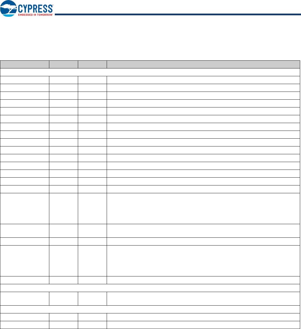
Pin Definitions
48-pin TQFP Package
Pin Name Pin No. Type
[1]
Description
Power and Clock
VCC_A 1 P V
CC_A
. 3.3 V analog power to the chip.
VCC_A 7 P V
CC_A
. 3.3 V analog power to the chip.
VCC_A 12 P V
CC_A
. 3.3 V analog power to the chip.
VCC_A 16 P V
CC_A
. 3.3 V analog power to the chip.
VCC_A 19 P V
CC_A
. 3.3 V analog power to the chip.
VCC_D 34 P V
CC_D
. 3.3 V digital power to the chip.
VCC_D 38 P V
CC_D
. 3.3 V digital power to the chip.
VCC 47 P V
CC
. 5 V input to the internal regulator; NC if using external regulator
VREG 48 P V
REG
. 5–3.3 V regulator o/p during internal regulation; NC if using external regulator.
GND 2 P GND. Connect to ground with as short a path as possible.
GND 8 P GND. Connect to ground with as short a path as possible.
GND 13 P GND. Connect to ground with as short a path as possible.
GND 20 P GND. Connect to ground with as short a path as possible.
XIN 14 I 12-MHz crystal clock input, or 12/27/48MHz clock input
XOUT 15 O 12-MHz Crystal OUT. (NC if external clock is used).
SEL48 / SEL27 25 / 44 I Clock source selection inputs.
00: Reserved
01: 48-MHz OSC-in
10: 27-MHz OSC-in
11: 12-MHz Crystal or OSC-in
RESET# 26 I Active LOW Reset. External reset input, default pull high 10 k; When RESET =
low, whole chip is reset to the initial state
SELFPWR 37 I Self Power. Input for selecting self/bus power. 0 is bus powered, 1 is self powered.
GANG 39 I/O GANG. Default is input mode after power-on-reset.
Gang Mode: Input:1 -> Output is 0 for normal operation and 1 for suspend
Individual Mode: Input:0 -> Output is 1 for normal operation and 0 for suspend
Refer to gang / individual power switching modes in Pin Configuration Options on
page 15 for details.
RREF 11 I/O 649
resistor must be connected between RREF and Ground.
System Interface
Test
I
2
C_SCL
27 I(R
DN
)
I/O(R
DN
)
Test. 0: Normal Operation and 1: Chip will be put in test mode.
I
2
C_SCL. Can be used as I
2
C clock pin to access I
2
C EEPROM.
Upstream Port
D– 3 I/O/Z Upstream D– Signal.
D+ 4 I/O/Z Upstream D+ Signal.
Note
1. Pin Types: I = Input, O = Output, P = Power/Ground, Z = High Impedance, R
DN
= Pad internal Pull Down Resistor, R
UP
= Pad internal Pull Up Resistor.