Document Number: 001-65659 Rev. *I Page 16 of 26
CY7C65642
Absolute Maximum Ratings
Exceeding maximum ratings may impair the useful life of the
device. These user guidelines are not tested.
Storage temperature ................................ –60 °C to +100 °C
Ambient temperature ..................................... 0 °C to +70 °C
5 V supply voltage to ground potential ........–0.5 V to +6.0 V
3.3 V supply voltage to ground potential .....–0.5 V to +3.6 V
Voltage at open drain input pins
(OVR#1-4, SELFPWR, RESET#) ................–0.5 V to +5.5 V
3.3 V Input Voltage for Digital I/O ................–0.5 V to +3.6 V
FOSC (oscillator or crystal frequency) ........12 MHz ± 0.05%
Operating Conditions
Ambient temperature ..................................... 0 °C to +70 °C
Ambient max junction temperature .............. 0 °C to +125 °C
5 V supply voltage to ground potential ......4.75 V to +5.25 V
3.3 V supply voltage to ground potential .....3.15 V to +3.6 V
Input voltage for USB signal pins ..................0.5 V to +3.6 V
Voltage at open drain input pins ..................–0.5 V to +5.0 V
Thermal characteristics 48-pin TQFP ...................78.7 °C/W
Thermal characteristics 28-pin QFN .....................33.3 °C/W
Document Number: 001-65659 Rev. *I Page 17 of 26
CY7C65642
Electrical Characteristics
DC Electrical Characteristics
Parameter Description Conditions Min Typ
Max
Unit
External regulator Internal regulator
P
D
Power dissipation Excluding USB signals 432 mW
V
IH
Input high voltage 2 V
V
IL
Input low voltage 0.8 V
I
l
Input leakage current
Full speed / low speed
(0 < V
IN
< V
CC
)
–10 +10 A
High speed mode
(0 < V
IN
< V
CC
)
–5 0 +5 A
V
OH
Output voltage high I
OH
= 8 mA 2.4 V
V
OL
Output low voltage I
OL
= 8 mA 0.4 V
R
DN
Pad internal pull-down resistor 29 59 135 
R
UP
Pad internal pull-up resistor 80 108 140 
C
IN
Input pin capacitance
Full speed / low speed
mode
–– 20 pF
high speed mode 4 4.5 5 pF
I
SUSP
Suspend current 0.786 1.043 1.3 mA
I
CC
Supply Current
4 Active ports
Full speed host,
full speed devices
88.7 103.9 105.4 mA
High speed host,
high speed devices
81.9 88.2 89.3 mA
High speed host,
full speed devices
88.2 101.2 102.3 mA
3 Active ports
[5]
Full speed host,
full speed devices
79.1 91.6 93 mA
High speed host,
high speed devices
72.9 78.5 78.6 mA
High speed host,
full speed devices
75.9 88.7 88.8 mA
2 Active ports
Full speed host,
full speed devices
68.1 78.4 78.6 mA
High speed host,
high speed devices
61.9 67.6 69.6 mA
High speed host,
full speed devices
64.9 75.4 76.1 mA
1 Active ports
Full speed host,
full speed devices
57.1 66.3 66.7 mA
High speed host,
high speed devices
51.9 57.6 59.3 mA
High speed host,
full speed devices
54.7 61.1 62.5 mA
No Active ports
[6]
Full speed host 42.8 48.9 50.3 mA
High speed host 44.2 49.1 50.6 mA
Notes
5. Current measurement is with device attached and enumerated.
6. No devices attached.
Document Number: 001-65659 Rev. *I Page 18 of 26
CY7C65642
AC Electrical Characteristics
USB Transceiver is USB 2.0 certified in low, full and high speed modes.
Both the upstream USB transceiver and all four downstream transceivers have passed the USB-IF USB 2.0 Electrical Certification
Testing.
The 48-pin TQFP package can support communication to EEPROM using either I
2
C or SPI. The 28-pin QFN package can support
only I
2
C communication to EEPROM.
AC characteristics of these two interfaces to EEPROM are summarized in tables below:
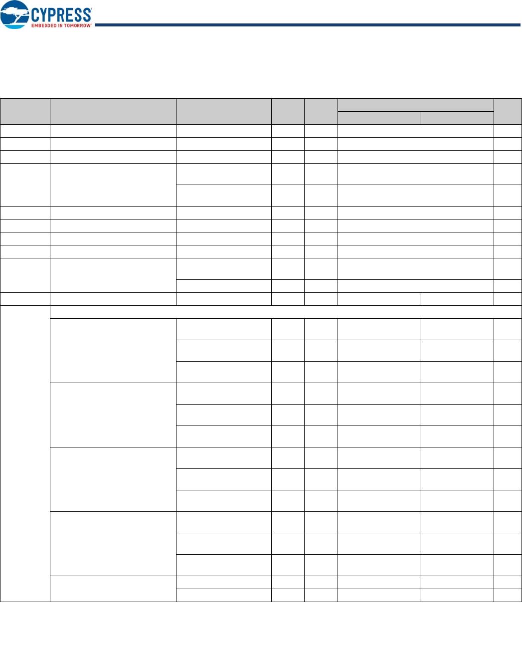
AC Characteristics of SPI EEPROM interface
Parameter Parameter Min Typ Max Units
t
CSS
CS setup time 3.0
µs
t
CSH
CS hold time 3.0
t
SKH
SK high time 1.0
t
SKL
SK low time 2.2
t
DIS
DI setup time 1.8
t
DIH
DI hold time 2.4
t
PD1
Output delay to ‘1’ 1.8
t
PD0
Output delay to ‘0’ 1.8
AC Characteristics of I
2
C EEPROM interface
Parameter Parameter
1.8 V–5.5 V 2.5 V–5.5 V
Units
Min Max Min Max
f
SCL
SCL clock frequency 0.0 100 0.0 400 KHz
t
LOW
Clock LOW Period 4.7 1.2 us
t
HIGH
Clock HIGH Period 4.0 0.6 us
t
SU:STA
Start condition setup time 4.7 0.6 us
t
SU:STO
Stop condition setup time 4.7 0.6 us
t
HD:STA
Start condition hold time 4.0 0.6 us
t
HD:STO
Stop condition hold time 4.0 0.6 us
t
SU:DAT
Data in setup time 200.0 100.0 ns
t
HD:DAT
Data in hold time 0 0 ns
t
DH
Data out hold time 100 50 ns
t
AA
Clock to output 0.1 4.5 0.1 us
t
WR
Write cycle time 10 5 ns
Thermal Resistance
Parameter Description
48-pin TQFP
Package
28-pin QFN
Package
Unit
JA
Thermal resistance (junction to ambient) 78.7 33.3 °C/W
JC
Thermal resistance (junction to case) 35.3 18.4 °C/W

CY7C65642-28LTXC

Mfr. #:
Manufacturer:
Cypress Semiconductor
Description:
USB Interface IC TetraHub Ctrl USB2.0
Lifecycle:
New from this manufacturer.
Delivery:
DHL FedEx Ups TNT EMS
Payment:
T/T Paypal Visa MoneyGram Western Union