AD7873 Data Sheet
Rev. F | Page 6 of 28
ABSOLUTE MAXIMUM RATINGS
T
A
= 25°C, unless otherwise noted.
Table 3.
Parameter Rating
+V
CC
to GND 0.3 V to +7 V
Analog Input Voltage to GND 0.3 V to V
CC
+ 0.3 V
Digital Input Voltage to GND 0.3 V to V
CC
+ 0.3 V
Digital Output Voltage to GND 0.3 V to V
CC
+ 0.3 V
V
REF
to GND 0.3 V to V
CC
+ 0.3 V
Input Current to Any Pin Except Supplies
1
±10 mA
Operating Temperature Range
Commercial (A, B Versions) –40°C to +85°C
Storage Temperature Range –65°C to +150°C
Junction Temperature 150°C
Power Dissipation 450 mW
IR Reflow Soldering
Peak Temperature
220°C (±5°C)
Time-to-Peak Temperature 10 sec to 30 sec
Ramp-Down Rate 6°C/sec max
Pb-free Parts Only
Peak Temperature 250°C
Time-to-Peak Temperature
20 sec to 40 sec
Ramp-Up Rate 3°C/sec max
Ramp-Down Rate 6°C/sec max
1
Transient currents of up to 100 mA do not cause SCR latch-up.
Stresses above those listed under Absolute Maximum Ratings
may cause permanent damage to the device. This is a stress
rating only; functional operation of the device at these or any
other conditions above those indicated in the operational
section of this specification is not implied. Exposure to absolute
maximum rating conditions for extended periods may affect
device reliability.
THERMAL RESISTANCE
θ
JA
is specified for the worst-case conditions, that is, a device
soldered in a circuit board for surface-mount packages.
Table 4. Thermal Resistance
Package Type θ
JA
θ
JC
Unit
16-Lead QSOP 149.97 38.8 °C/W
16-Lead TSSOP 150.4 27.6 °C/W
16-Lead LFCSP 135.7 °C/W
ESD CAUTION
Data Sheet AD7873
Rev. F | Page 7 of 28
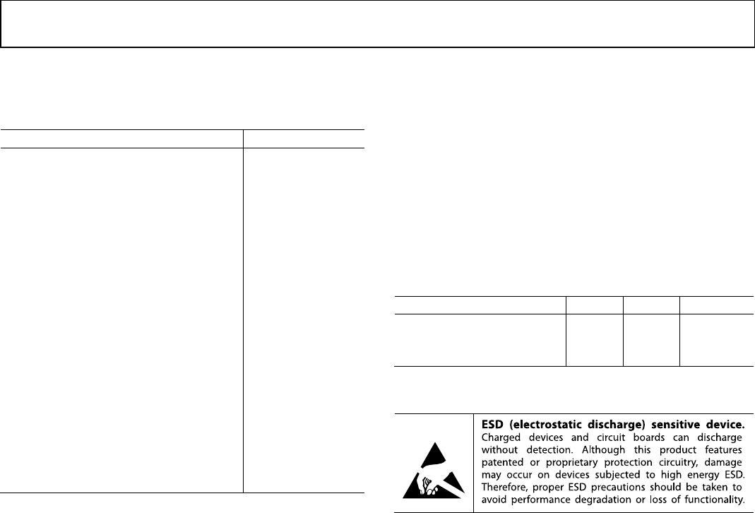
PIN CONFIGURATIONS AND FUNCTION DESCRIPTIONS
Figure 3. LFCSP Pin Configuration
Figure 4. QSOP/TSSOP Pin Configuration
Table 5. Pin Function Descriptions
Pin No.
Mnemonic
Description
LFCSP
QSOP/
TSSOP
3, 10 1, 10 +V
CC
Power Supply Input. The +V
CC
range for the AD7873 is from 2.2 V to 5.25 V. Both +V
CC
pins should be
connected directly together.
11 2 X+ X+ Position Input. ADC Input Channel 1.
12 3 Y+ Y+ Position Input. ADC Input Channel 2.
13 4 X– X– Position Input.
14 5 Y– Y– Position Input. ADC Input Channel 3.
15 6 GND
Analog Ground. Ground reference point for all circuitry on the AD7873. All analog input signals
and any external reference signals should be referred to this GND voltage.
16 7 V
BAT
Battery Monitor Input. ADC Input Channel 4.
1 8 AUX Auxiliary Input. ADC Input Channel 5.
2 9 V
REF
Reference Output for the AD7873. Alternatively, an external reference can be applied to this input.
The voltage range for the external reference is 1.0 V to +V
CC
. For specified performance, it is 2.5 V on
the AD7873. The internal 2.5 V reference is available on this pin for use external to the device. The
reference output must be buffered before it is applied elsewhere in a system. A 0.1 µF capacitor is
recommended between this pin and GND to reduce system noise effects.
4 11
PENIRQ
Pen Interrupt. CMOS logic open-drain output (requires 10 kΩ to 100 kΩ pull-up resistor externally).
5 12 DOUT
Data Out. Logic output. The conversion result from the AD7873 is provided on this output as a
serial data stream. The bits are clocked out on the falling edge of the DCLK input. This output is
high impedance when
CS is high.
6 13 BUSY
BUSY Output. Logic output. This output is high impedance when
CS is high.
7 14 DIN
Data In. Logic Input. Data to be written to the AD7873 control register is provided on this input and
is clocked into the register on the rising edge of DCLK (see the Control Register section).
8 15
CS Chip Select Input. Active low logic input. This input provides the dual function of initiating
conversions on the AD7873 and enabling the serial input/output register.
9 16 DCLK
External Clock Input. Logic input. DCLK provides the serial clock for accessing data from the part.
This clock input is also used as the clock source for the AD7873 conversion process.
N/A
1
EPAD
Exposed Pad. The exposed pad is not connected internally. For increased reliability of the solder
joints and maximum thermal capability, it is recommended that the pad be soldered to the ground
plane.
1
N/A = not applicable.
AUX
V
REF
+V
CC
PENIRQ
X+
Y+
+V
CC
DCLK
DOUT
BUSY
DIN
CS
GND
V
BAT
Y–
X–
02164-003
12
11
10
1
3
4
9
2
6
5
7
8
16
15
14
13
NOTES
1. THE EXPOSED PAD IS NOT CONNECTED INTERNALLY.
FOR INCREASED RELIABILITY OF THE SOLDER JOINTS
AND MAXIMUM THERMAL CAPABILITY, IT IS
RECOMMENDED THAT THE PAD BE SOLDERED
TO GROUND PLANE.
AD7873
TOP VIEW
1
2
3
4
5
6
7
8
16
15
14
13
12
11
10
9
X+
Y+
X–
V
BAT
GND
Y–
+V
CC
CS
DIN
BUSY
+V
CC
AUX V
REF
PENIRQ
DOUT
DCLK
AD7873
TOP VIEW
(Not to Scale)
02164-004
AD7873 Data Sheet
Rev. F | Page 8 of 28
TERMINOLOGY
Integral Nonlinearity
Integral nonlinearity is the maximum deviation from a straight
line passing through the endpoints of the ADC transfer function.
The endpoints of the transfer function are zero scale, a point 1 LSB
below the first code transition, and full scale, a point 1 LSB
above the last code transition.
Differential Nonlinearity
Differential nonlinearity is the difference between the measured
and the ideal 1 LSB change between any two adjacent codes in
the ADC.
Offset Error
Offset error is the deviation of the first code transition (00000)
to (00001) from the ideal, that is, AGND + 1 LSB.
Gain Error
Gain error is the deviation of the last code transition (111110)
to (111111) from the ideal (that is, V
REF
1 LSB) after the
offset error is adjusted out.
Track-and-Hold Acquisition Time
The track-and-hold amplifier enters the acquisition phase on
the fifth falling edge of DCLK after the start bit has been
detected. Three DCLK cycles are allowed for the track-and-hold
acquisition time. The input signal is fully acquired to the 12-bit
level within this time even with the maximum specified DCLK
frequency. See the Analog Input section for more details.
On Resistance
On resistance is a measure of the ohmic resistance between the
drain and source of the switch drivers.

AD7873BRQZ-REEL

Mfr. #:
Manufacturer:
Analog Devices Inc.
Description:
Touch Screen Controllers 27V 12-BIT TouchScrn Digitizer
Lifecycle:
New from this manufacturer.
Delivery:
DHL FedEx Ups TNT EMS
Payment:
T/T Paypal Visa MoneyGram Western Union