LT3582/LT3582-5/LT3582-12
4
3582512fb
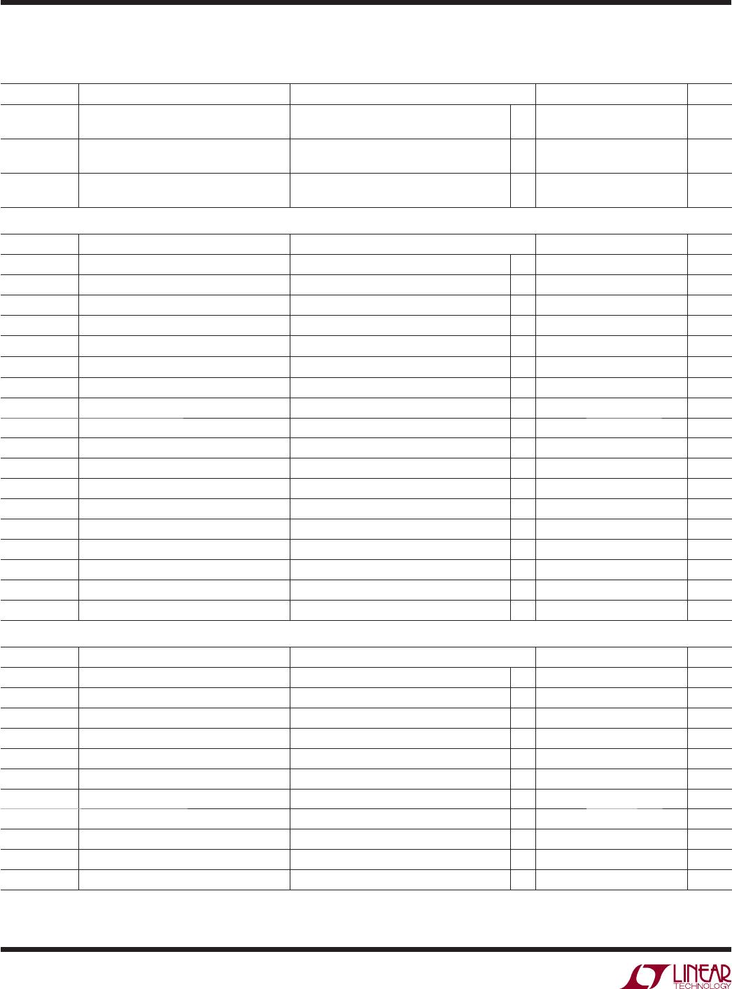
SYMBOL PARAMETER CONDITIONS MIN TYP MAX UNITS
I
RAMP10
RAMPP/RAMPN Pull-Up Current (Note 2)
IRMP Code = 10
V
RAMPP
= 0.0V
V
RAMPN
= 0.0V
l
2.8 4.0 5.2 µA
I
RAMP11
RAMPP/RAMPN Pull-Up Current (Note 2)
IRMP Code = 11
V
RAMPP
= 0.0V
V
RAMPN
= 0.0V
l
5.6 8.0 10.4 µA
V
VPLUS
V
OUTP
Voltage Increase When V
PLUS
Bit is
Set from 0 to 1 (Note 2)
25 mV
Input/Output Pin Characteristics
SYMBOL PARAMETER CONDITIONS MIN TYP MAX UNITS
V
SHDN_VIH
SHDN Input Voltage High
l
1.1 V
V
SHDN_VIL
SHDN Input Voltage Low
l
0.3 V
V
HYST_SHDN
SHDN Input Hysteresis 50 mV
I
SHDN_BIAS
SHDN Pin Bias Current V
SHDN
= 1V 2.5 4.5 6.5 µA
V
CA_VIH
CA Input Voltage High
l
0.7 × V
IN
V
V
CA_VIL
CA Input Voltage Low
l
0.3 × V
IN
V
V
SDA_VIH
SDA Input Voltage High
l
1.25 V
V
SDA_VIL
SDA Input Voltage Low
l
0.85 V
V
SCL_VIH
SCL Input Voltage High
l
1.25 V
V
SCL_VIL
SCL Input Voltage Low
l
0.85 V
V
HYST
Input Hysteresis SDA, SCL Pins 80 mV
I
LEAK_CA
CA Input Leakage Current CA = 0V and 5.5V
l
±1 µA
I
LEAK_SCL
SCL Input Leakage Current SCL = 0V and 5.5V
l
±1 µA
I
LEAK_SDA
SDA Input Leakage Current SDA = 0V and 5.5V
l
±1 µA
C
IN
Input Capacitance SDA, SCL Pins 3 pF
V
SDA_OL
SDA Output Low Voltage 3mA into SDA Pin
l
0.4 V
V
PP_RANGE
V
PP
Voltage Range for OTP Write (Note 2) 13 15 V
V
PPUVLO
Undervoltage Lockout for V
PP
Pin (Note 2)
l
12.05 12.45 12.85 V
I
2
C Timing Characteristics
SYMBOL PARAMETER CONDITIONS MIN TYP MAX UNITS
f
SCL
Serial Clock Frequency
l
100 kHz
t
LOW
Serial Clock Low Period
l
4.7 µs
t
HIGH
Serial Clock High Period
l
4.0 µs
t
BUF
Bus Free Time Between Stop and Start
l
4.7 µs
t
HD,STA
Start Condition Hold Time
l
4.0 µs
t
SU,STA
Start Condition Setup Time
l
4.7 µs
t
SU,STO
Stop Condition Setup Time
l
4.0 µs
t
HD,DATXMIT
Data Hold Time Transmitting LT3582 Sending Data to Host
l
300 ns
t
HD,DATRCV
Data Hold Time Receiving LT3582 Receiving Data from Host
l
0ns
t
SU,DAT
Data Setup Time
l
250 ns
t
F
SDA Fall Time 400pF Load, V
IN
≥ 2.5V
l
250 ns
ELECTRICAL CHARACTERISTICS
The l denotes the specifi cations which apply over the full operating
temperature range, otherwise specifi cations are at T
A
= 25°C. V
IN
= 3.6V, V
SHDN
= V
IN
unless otherwise noted. (Note 3)
Programmable Output Characteristics