SC18IM700_3 All information provided in this document is subject to legal disclaimers. © NXP Semiconductors N.V. 2017. All rights reserved.
Product data sheet Rev. 3 — 12 October 2017 19 of 24
NXP Semiconductors
SC18IM700
Master I
2
C-bus controller with UART interface
14.4 Reflow soldering
Key characteristics in reflow soldering are:
Lead-free versus SnPb soldering; note that a lead-free reflow process usually leads to
higher minimum peak temperatures (see Figure 19
) than a SnPb process, thus
reducing the process window
Solder paste printing issues including smearing, release, and adjusting the process
window for a mix of large and small components on one board
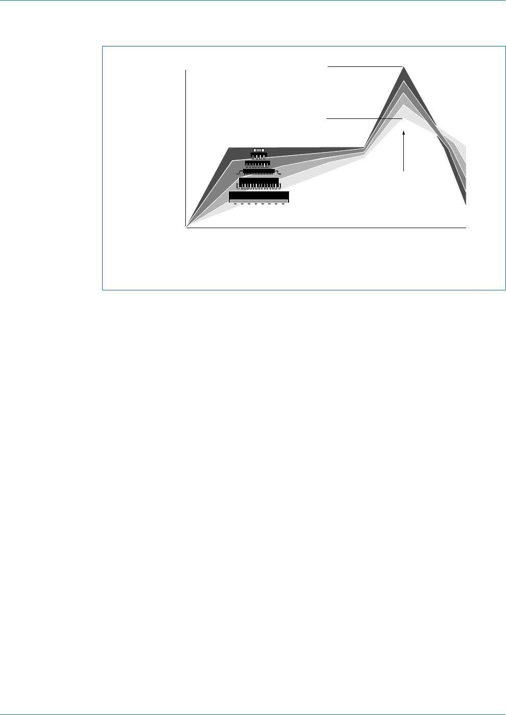
Reflow temperature profile; this profile includes preheat, reflow (in which the board is
heated to the peak temperature) and cooling down. It is imperative that the peak
temperature is high enough for the solder to make reliable solder joints (a solder paste
characteristic). In addition, the peak temperature must be low enough that the
packages and/or boards are not damaged. The peak temperature of the package
depends on package thickness and volume and is classified in accordance with
Table 14
and 15
Moisture sensitivity precautions, as indicated on the packing, must be respected at all
times.
Studies have shown that small packages reach higher temperatures during reflow
soldering, see Figure 19
.
Table 14. SnPb eutectic process (from J-STD-020C)
Package thickness (mm) Package reflow temperature (C)
Volume (mm
3
)
< 350 350
< 2.5 235 220
2.5 220 220
Table 15. Lead-free process (from J-STD-020C)
Package thickness (mm) Package reflow temperature (C)
Volume (mm
3
)
< 350 350 to 2000 > 2000
< 1.6 260 260 260
1.6 to 2.5 260 250 245
> 2.5 250 245 245
SC18IM700_3 All information provided in this document is subject to legal disclaimers. © NXP Semiconductors N.V. 2017. All rights reserved.
Product data sheet Rev. 3 — 12 October 2017 20 of 24
NXP Semiconductors
SC18IM700
Master I
2
C-bus controller with UART interface
For further information on temperature profiles, refer to Application Note AN10365
“Surface mount reflow soldering description”.
MSL: Moisture Sensitivity Level
Fig 19. Temperature profiles for large and small components
001aac844
temperature
time
minimum peak temperature
= minimum soldering temperature
maximum peak temperature
= MSL limit, damage level
peak
temperature
SC18IM700_3 All information provided in this document is subject to legal disclaimers. © NXP Semiconductors N.V. 2017. All rights reserved.
Product data sheet Rev. 3 — 12 October 2017 21 of 24
NXP Semiconductors
SC18IM700
Master I
2
C-bus controller with UART interface
15. Abbreviations
16. Revision history
Table 16. Abbreviations
Acronym Description
ASCII American Standard Code for Information Interchange
FIFO First In, First Out
GPIO General Purpose Input/Output
I
2
C-bus Inter Integrated Circuit bus
RX FIFO Receive FIFO
TX FIFO Transmit FIFO
UART Universal Asynchronous Receiver/Transmitter
Table 17. Revision history
Document ID Release date Data sheet status Change notice Supersedes
SC18IM700_3 20171012 Product data sheet 201708035I
SC18IM700_2
Modifications:
Added SC18IM700/S8
Updated Section 4.1 “Ordering options
Section 2 “Features and benefits: 9
th
bullet item: changed from “2.3 V and 3.6 V operation” to
“2.4 V and 3.6 V operation”
Table 5 “Internal registers summary:
changed Default value for register IOState from “0x0F” to “-”
added Table note [1]
SC18IM700_2 20070810 Product data sheet - SC18IM700_1
SC18IM700_1 20060228 Product data sheet - -

SC18IM700IPW/S8HP

Mfr. #:
Manufacturer:
NXP Semiconductors
Description:
I/O Controller Interface IC Master I2C-bus Controller w/UART
Lifecycle:
New from this manufacturer.
Delivery:
DHL FedEx Ups TNT EMS
Payment:
T/T Paypal Visa MoneyGram Western Union

Products related to this Datasheet