SC18IM700_3 All information provided in this document is subject to legal disclaimers. © NXP Semiconductors N.V. 2017. All rights reserved.
Product data sheet Rev. 3 — 12 October 2017 4 of 24
NXP Semiconductors
SC18IM700
Master I
2
C-bus controller with UART interface
7. Functional description
The SC18IM700 is a bridge between a UART port and I
2
C-bus. The UART interface
consists of a full-functional advanced UART. The UART communicates with the host
through the TX and RX pins. The serial data format is fixed: one start bit, 8 data bits, and
one stop bit. After reset the baud rate defaults to 9600 bit/s, and can be changed through
the Baud Rate Generator (BRG) registers.
After a power-up sequence or a hardware reset, the SC18IM700 will send two continuous
bytes to the host to indicate a start-up condition. These two bytes are 0x4F and 0x4B;
‘OK’ in ASCII.
7.1 UART message format
The host initiates an I
2
C-bus data transfer, reads from and writes to SC18IM700 internal
registers through a series of ASCII commands. Table 4
lists the ASCII commands
supported by SC18IM700, and also their hexadecimal value representation.
Unrecognized commands are ignored by the device.
To prevent the host from handing the SC18IM700 due to an unfinished command
sequence, the SC18IM700 has a time-out feature. The delay between any two bytes of
data coming from the host should be less than 655 ms. If this condition is not met, the
SC18IM700 will time-out and clear the receive buffer. The SC18IM700 then starts to wait
for the next command from the host.
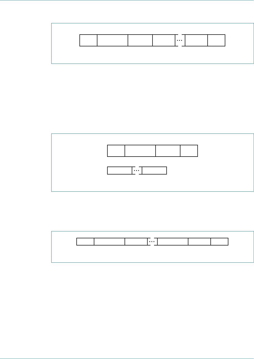
7.1.1 Write N bytes to slave device
The host issues the write command by sending an S character followed by an I
2
C-bus
slave device address, the total number of bytes to be sent, and I
2
C-bus data which begins
with the first byte (DATA 0) and ends with the last byte (DATA N). The frame is then
terminated with a P character. Once the host issues this command, the SC18IM700 will
access the I
2
C-bus slave device and start sending the I
2
C-bus data bytes.
Note that the second byte sent is the I
2
C-bus device slave address. The least significant
bit (W) of this byte must be set to 0 to indicate this is an I
2
C-bus write command.
Table 4. ASCII commands supported by SC18IM700
ASCII command Hex value Command function
S0x53I
2
C-bus START
P0x50I
2
C-bus STOP
R 0x52 read SC18IM700 internal register
W 0x57 write to SC18IM700 internal register
I 0x49 read GPIO port
O 0x4F write to GPIO port
Z 0x5A power down