AD7152/AD7153 Data Sheet
Rev. A | Page 16 of 24
CAP SETUP REGISTERS
Address 0x0B for Channel 1
Address 0x0E Channel 2 (AD7152 Only)
Default Value 0x00
Table 10. CAP Setup Register Bit Map
Bit Bit 7 Bit 6 Bit 5 Bit 4 Bit 3 Bit 2 Bit 1 Bit 0
Mnemonic Range 1 Range 0 CAPDIFF Unused Unused Unused Unused Unused
Default 0 0 0 0 0 0 0 0
Table 11. CAP Setup Register Bit Descriptions
Bit Mnemonic Description
7 Range 1 Capacitive input range and mode setup
6 Range 0
Range 1 Range 0
Capacitive Input Range
5 CAPDIFF
CAPDIFF = 1 (Differential Mode) CAPDIFF = 0 (Single-Ended Mode)
0
0
±1 pF
2 pF
0 1 ±0.25 pF 0.5 pF
1 0 ±0.5 pF 0.25 pF
1 1 ±2 pF 4 pF
4 to 0 N/A These bits must be 0 for proper operation
CONFIGURATION REGISTER
Address Pointer 0x0F
Default Value 0x00
Table 12. Configuration Register Bit Map
Bit Bit 7 Bit 6 Bit 5 Bit 4 Bit 3 Bit 2 Bit 1 Bit 0
Mnemonic Unused Unused Unused Ch1en Ch2en MD2 MD1 MD0
Default 0 0 0 0 0 0 0 0
Table 13. Configuration Register Bit Descriptions
Bit
Mnemonic
Description
7 to 5 N/A These bits must be 0 for proper operation
4
Ch1en
Ch2en = 1 enables Channel 1 for single conversion, continuous conversion, or calibration
3 Ch2en Ch2en = 1 enables Channel 2 for single conversion, continuous conversion, or calibration
2 MD2 Converter mode of operation setup
1
MD1
MD2 MD1 MD0 Mode
0 MD0 0 0 0 Idle
0
0
1
Continuous conversion
0 1 0 Single conversion
0 1 1 Power-down
1 0 0 N/A
1 0 1 Capacitance system offset calibration
1
1
0
Capacitance system gain calibration
1 1 1 N/A
Data Sheet AD7152/AD7153
Rev. A | Page 17 of 24
CAPDAC POS REGISTER
Address 0x11
Default Value 0x00
Table 14. Status Register Bit Map
Bit Bit 7 Bit 6 Bit 5 Bit 4 Bit 3 Bit 2 Bit 1 Bit 0
Mnemonic DACPen Unused Unused DACP – Bits[4:0] Value
Default 0 0 0 0x00
Table 15. Status Register Bit Descriptions
Bit Mnemonic Description
7
DACPen
DACPen = 1 connects the capacitive DAC POS to the positive capacitive input
6 to 5 N/A These bits must be 0 for proper operation
4 to 0 DACP DACP value, Code 0x00 = 0 pF, Code 0x1F = full range
CAPDAC NEG REGISTER
Address 0x12
Default Value 0x00
Table 16. Status Register Bit Map
Bit Bit 7 Bit 6 Bit 5 Bit 4 Bit 3 Bit 2 Bit 1 Bit 0
Mnemonic DACNen Unused Unused DACN Bit[4:0] Value
Default 0 0 0 0x00
Table 17. Status Register Bit Descriptions
Bit Mnemonic Description
7 DACNen DACNen = 1 connects the capacitive DAC NEG to the positive capacitive input
6 to 5 N/A These bits must be 0 for proper operation
4 to 0 DACN DACN value, Code 0x00 = 0 pF, Code 0x1F = full range
CONFIGURATION2 REGISTER
Address 0x1A,
Default Value 0x00
Table 18. Configuration2 Register Bit Map
Bit Bit 7 Bit 6 Bit 5 Bit 4 Bit 3 Bit 2 Bit 1 Bit 0
Mnemonic Unused Unused OSR1 OSR0
Default 0 0 0 0 0 0 0 0
Table 19. Configuration2 Register Bit Descriptions
Bit Mnemonic Description
7 to 6 N/A These bits must be 0 for proper operation
5
4
OSR1
OSR0
Capacitive channel digital filter setup; conversion time/update rate setup per channel
OSR1 OSR0 Conversion Time (ms) Update Rate (Hz)
0 0 5 200
0 1 20 50
1 0 50 20
1
1
60
16.7
3 to 0 N/A These bits must be 0 for proper operation
AD7152/AD7153 Data Sheet
Rev. A | Page 18 of 24
CIRCUIT DESCRIPTION
DIGITAL
FILTER
12-BIT Σ-
MODULATOR
CLOCK
GENERATOR
VOLTAGE
REFERENCE
AD7152
I
2
C
SERIAL
INTERFACE
07450-025
EXCITATION
EXC2
CIN1(+)
CIN1(–)
CIN2(+)
CIN2(–)
EXC1
SDA
SCL
V
DD
GND
CONTROL LOGIC
CALIBRATION
CAP+
CAP–
MUX
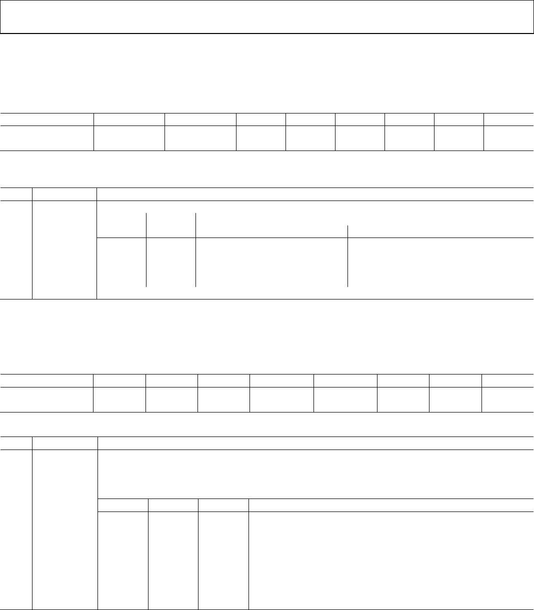
Figure 25. AD7152 Block Diagram
DIGITAL
FILTER
12-BIT Σ-
MODULATOR
CLOCK
GENERATOR
VOLTAGE
REFERENCE
AD7153
I
2
C
SERIAL
INTERFACE
07450-026
EXCITATION
CIN1(+)
CIN1(–)
EXC1
SDA
SCL
V
DD
GND
CONTROL LOGIC
CALIBRATION
CAP+
CAP–
MUX
Figure 26. AD7153 Block Diagram
The core of the AD7152/AD7153 is a precision converter
consisting of a second-order modulator (Σ-Δ or charge-
balancing) and a third-order digital filter.
In addition to the converter, the AD7152/AD7153 integrate a
multiplexer, an excitation source, and CAPDACs for the capaci-
tive inputs, a voltage reference, a complete clock generator, a
control and calibration logic, and an I
2
C-compatible serial
interface.
The AD7153 has one capacitive input, while the AD7152 has
two capacitive inputs. For the AD7152, the modulator input and
the excitation source are multiplexed between the converting
channel. All other features and specifications are identical for
both devices.
CAPACITANCE-TO-DIGITAL CONVERTER (CDC)
Figure 27 shows the CDC simplified functional diagram. The
measured capacitance C
X
is connected between the excitation
source and the Σ-Δ modulator input. A square-wave excitation
signal is applied on the C
X
during the conversion and the mod-
ulator continuously samples the charge going through the C
X
.
The digital filter processes the modulator output, which is a
stream of 0s and 1s containing the information in 0 and 1
density. The data from the digital filter is scaled, applying the
calibration coefficients, and the final result can be read through
the serial interface. The AD7152/AD7153 are designed for
floating capacitive sensors. Therefore, both C
X
plates have to
be isolated from ground.
DIGITAL
FILTER
12-BIT Σ-
MODULATOR
CLOCK
GENERATOR
CAPACITANCE-TO-DIGITAL CONVERTER
(CDC)
07450-027
EXCITATION
DATA
EXC
CIN
C
X
Figure 27. CDC Simplified Block Diagram
EXCITATION SOURCE
The AD7152/AD7153 have one excitation source. For the
AD7152, the excitation source is switched between the
excitation pins, EXC1 and EXC2, depending on which
channel performs a conversion.

AD7153BRMZ-REEL

Mfr. #:
Manufacturer:
Analog Devices Inc.
Description:
Data Acquisition ADCs/DACs - Specialized 1-CH 12-bit CDC IC
Lifecycle:
New from this manufacturer.
Delivery:
DHL FedEx Ups TNT EMS
Payment:
T/T Paypal Visa MoneyGram Western Union

Products related to this Datasheet