REV. B
Information furnished by Analog Devices is believed to be accurate and
reliable. However, no responsibility is assumed by Analog Devices for its
use, nor for any infringements of patents or other rights of third parties
which may result from its use. No license is granted by implication or
otherwise under any patent or patent rights of Analog Devices.
a
AD7865
One Technology Way, P.O. Box 9106, Norwood, MA 02062-9106, U.S.A.
Tel: 781/329-4700 World Wide Web Site: http://www.analog.com
Fax: 781/326-8703 © Analog Devices, Inc., 2000
Four-Channel, Simultaneous
Sampling, Fast, 14-Bit ADC
FEATURES
Fast (2.4 s) 14-Bit ADC
Four Simultaneously Sampled Inputs
Four Track/Hold Amplifiers
0.35 s Track/Hold Acquisition Time
2.4 s Conversion Time per Channel
HW/SW Select of Channel Sequence for Conversion
Single Supply Operation
Selection of Input Ranges: 10 V, 5 V and 2.5 V,
0 V to 5 V and 0 V to 2.5 V
High Speed Parallel Interface Which Also Allows
Interfacing to 3 V Processors
Low Power, 115 mW Typ
Power Saving Mode, 15 W Typ
Overvoltage Protection on Analog Inputs
APPLICATIONS
AC Motor Control
Uninterruptible Power Supplies
Industrial Power Meters/Monitors
Data Acquisition Systems
Communications
GENERAL DESCRIPTION
The AD7865 is a fast, low power, four-channel simultaneous
sampling 14-bit A/D converter that operates from a single 5 V
supply. The part contains a 2.4 µs successive approximation
ADC, four track/hold amplifiers, 2.5 V reference, on-chip clock
oscillator, signal conditioning circuitry and a high speed parallel
interface. The input signals on four channels are sampled simul-
taneously thus preserving the relative phase information of the
signals on the four analog inputs. The part accepts analog input
ranges of ±10 V, ±5 V, ± 2.5 V, 0 V to 2.5 V and 0 V to 5 V.
The part allows any subset of the four channels to be converted
in order to maximize the throughput rate on the selected sequence.
The channels to be converted can be selected either via hard-
ware (channel select input pins) or via software (programming
the channel select register).
A single conversion start signal (CONVST) simultaneously places
all the track/holds into hold and initiates conversion sequence
for the selected channels. The EOC signal indicates the end of
each individual conversion in the selected conversion sequence.
The BUSY signal indicates the end of the conversion sequence.
Data is read from the part via a 14-bit parallel data bus using the
standard CS and RD signals. Maximum throughput for a single
channel is 350 kSPS. For all four channels the maximum through-
put is 100 kSPS.
The AD7865 is available in a small (0.3 sq. inch area) 44-lead
PQFP.
PRODUCT HIGHLIGHTS
1. The AD7865 features four Track/Hold amplifiers and a fast
(2.4 µs) ADC allowing simultaneous sampling and then con-
version of any subset of the four channels.
2. The AD7865 operates from a single 5 V supply and con-
sumes only 115 mW typ, making it ideal for low power and
portable applications.
3. The part offers a high speed parallel interface for easy con-
nection to microprocessors, microcontrollers and digital
signal processors.
4. The part is offered in three versions with different analog
input ranges. The AD7865-1 offers the standard industrial
ranges of ±10 V and ± 5 V; the AD7865-2 offers a unipolar
range of 0 V to 2.5 V or 0 V to 5 V and the AD7865-3 offers
the common signal processing input range of ± 2.5 V.
5. The part features very tight aperture delay matching between
the four input sample and hold amplifiers.
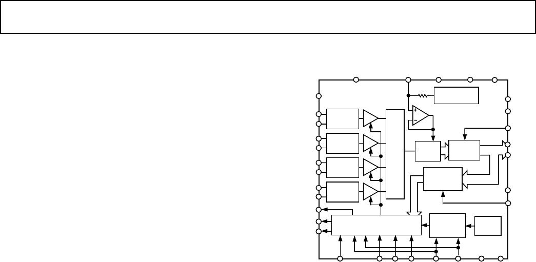
FUNCTIONAL BLOCK DIAGRAM
SIGNAL
SCALING
SIGNAL
SCALING
SIGNAL
SCALING
SIGNAL
SCALING
FRSTDATA
AGND
CHANNEL
SELECT
REGISTER
MUX
DB0–DB3
+2.5V
REFERENCE
TRACK/HOLD
4
6k
AD7865
EOC
V
DRIVE
RD
CLK IN
/SL1
INT/EXT
CLK/SL2
SL3 SL4
H/S
SEL
DGND
AV
DD
V
REF
AGND
CONVST
BUSY
DB13
DV
DD
V
IN4A
V
IN3B
V
IN3A
V
IN2B
V
IN1B
STBY
V
REFAGND
AGND
V
IN1A
V
IN2A
14-BIT
ADC
CONVERSION
CONTROL LOGIC
INT
CLOCK
INT/EXT
CLOCK
SELECT
OUTPUT
LATCH
WR
CS
DB0
V
IN4B