REV. B
AD7865
–18–
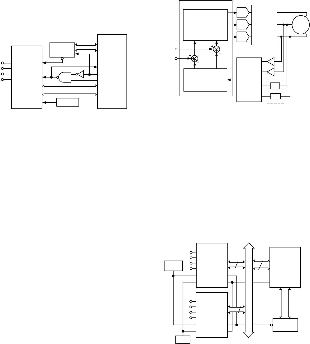
The MC68000 AS and R/W outputs are used to generate a
separate RD input signal for the AD7865. CS is used to drive
the 68000 DTACK input to allow the processor to execute a
normal read operation to the AD7865. The conversion results
are read using the following 68000 instruction:
MOVE.W ADC,D0
where D0 is the 68000 D0 register and ADC is the AD7865
address.
CS
RD
CONVST
DB0–DB13
AD7865
V
IN1
V
IN2
V
IN3
V
IN4
DTACK
AS
D0–D13
A0–A15
MC68000
ADDRESS
DECODE
CLOCK
R/W
Figure 21. AD7865–MC68000 Interface
Vector Motor Control
The current drawn by a motor can be split into two compo-
nents: one produces torque and the other produces magnetic
flux. For optimal performance of the motor, these two compo-
nents should be controlled independently. In conventional
methods of controlling a three-phase motor, the current (or
voltage) supplied to the motor and the frequency of the drive are
the basic control variables. However, both the torque and flux
are functions of current (or voltage) and frequency. This cou-
pling effect can reduce the performance of the motor because,
for example, if the torque is increased by increasing the fre-
quency, the flux tends to decrease.
Vector control of an ac motor involves controlling phase in
addition to drive and current frequency. Controlling the phase
of the motor requires feedback information on the position of
the rotor relative to the rotating magnetic field in the motor.
Using this information, a vector controller mathematically trans-
forms the three phase drive currents into separate torque and
flux components. The AD7865, with its four-channel simulta-
neous sampling capability, is ideally suited for use in vector
motor control applications.
A block diagram of a vector motor control application using the
AD7865 is shown in Figure 22. The position of the field is
derived by determining the current in each phase of the motor.
Only two phase currents need to be measured because the third
can be calculated if two phases are known. V
IN1
and V
IN2
of the
AD7865 are used to digitize this information.
Simultaneous sampling is critical to maintain the relative phase
information between the two channels. A current sensing isola-
tion amplifier, transformer or Hall-effect sensor is used between
the motor and the AD7865. Rotor information is obtained by
measuring the voltage from two of the inputs to the motor. V
IN3
and V
IN4
of the AD7865 are used to obtain this information.
Once again, the relative phase of the two channels is important.
A DSP microprocessor is used to perform the mathematical
transformations and control loop calculations on the informa-
tion fed back by the AD7865.
DAC
DSP MICROPROCESSOR
DAC
DAC
DRIVE
CIRCUITRY
3-
PHASE
MOTOR
I
C
I
B
I
A
V
B
V
A
AD7865*
V
IN1
V
IN2
V
IN3
V
IN4
ISOLATION
AMPLIFIERS
VOLTAGE
ATTENUATORS
TORQUE
SETPOINT
FLUX
SETPOINT
*ADDITIONAL PINS OMITTED FOR CLARITY
TORQUE AND FLUX
CONTROL LOOP
CALCULATIONS AND
TWO-TO-THREE-
PHASE INFORMATION
TRANSFORMATION
TO TORQUE AND
FLUX CURRENT
COMPONENTS
Figure 22. Vector Motor Control Using the AD7865
MULTIPLE AD7865s IN A SYSTEM
Figure 23 shows a system where a number of AD7865s can be
configured to handle multiple input channels. This type of con-
figuration is common in applications such as sonar, radar, etc.
The AD7865 is specified with maximum limits on aperture
delay match. This means that the user knows the difference in
the sampling instant between all channels. This allows the user
to maintain relative phase information between the different
channels. The AD7865 has a maximum aperture delay match-
ing of ±4 ns.
All AD7865s use the same external SAR clock (5 MHz). There-
fore, the conversion time for all devices will be the same and so
all devices may be read simultaneously. In the example shown in
Figure 23, the data outputs of two AD7865s are enabled onto a
32-bit wide data bus when EOC goes low.
14
32
14
ADSP-2106x
RD
EOC
AD7865
V
IN1
V
IN2
V
IN3
V
IN4
V
REF
CLK IN
CS
RD
ADDRESS
DECODE
AD7865
V
IN1
V
IN2
V
IN3
V
IN4
V
REF
CLK IN
CS
RD
5MHz
AD780
Figure 23. Multiple AD7865s in Multichannel System
