PCB Layout and Routing
Careful PCB layout is important for proper operation.
Use the following guidelines for good PCB layout:
• Minimize the area of the high current-switching loop
of the rectifier diode, switching FET, sense resistor,
and output capacitor to avoid excessive switching
noise. Use wide and short traces for the gate-drive
loop from DL, to the FET gate, and through the cur-
rent-sense resistor, then returning to the IC PGND
and GND.
• Connect high-current input and output components
with short and wide connections. The high-current
input loop is from the positive terminal of the input
capacitor to the inductor, to the switching FET, to
the current-sense resistor, and to the negative ter-
minal of the input capacitor. The high-current output
loop is from the positive terminal of the input capac-
itor to the inductor, to the rectifier diode, to the posi-
tive terminal of the output capacitor, reconnecting
between the output capacitor and input capacitor
ground terminals. Avoid using vias in the high-cur-
rent paths. If vias are unavoidable, use multiple vias
in parallel to reduce resistance and inductance.
• Place the feedback and even voltage-divider resis-
tors as close to FB and OVP as possible. The
divider center trace should be kept short. Placing
the resistors far away causes the sensing trace to
become antennas that can pick up switching noise.
Avoid running the sensing traces near drain con-
nection of the switching FET.
• Place the input bypass capacitor as close to the
device as possible. The ground connection of the
bypass capacitor should be connected directly to
GND with a wide trace.
• Minimize the size of the switching FET drain node
while keeping it wide and short. Keep the drain
node away from the feedback node and ground. If
possible, avoid running this node from one side of
the PCB to the other. Use DC traces as shields, if
necessary.
• Provide large enough cooling copper traces for the
external current sink FETs. Calculate the worst-case
power dissipation and allocate sufficient area for
cooling.
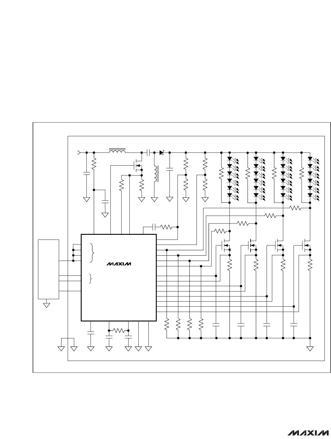
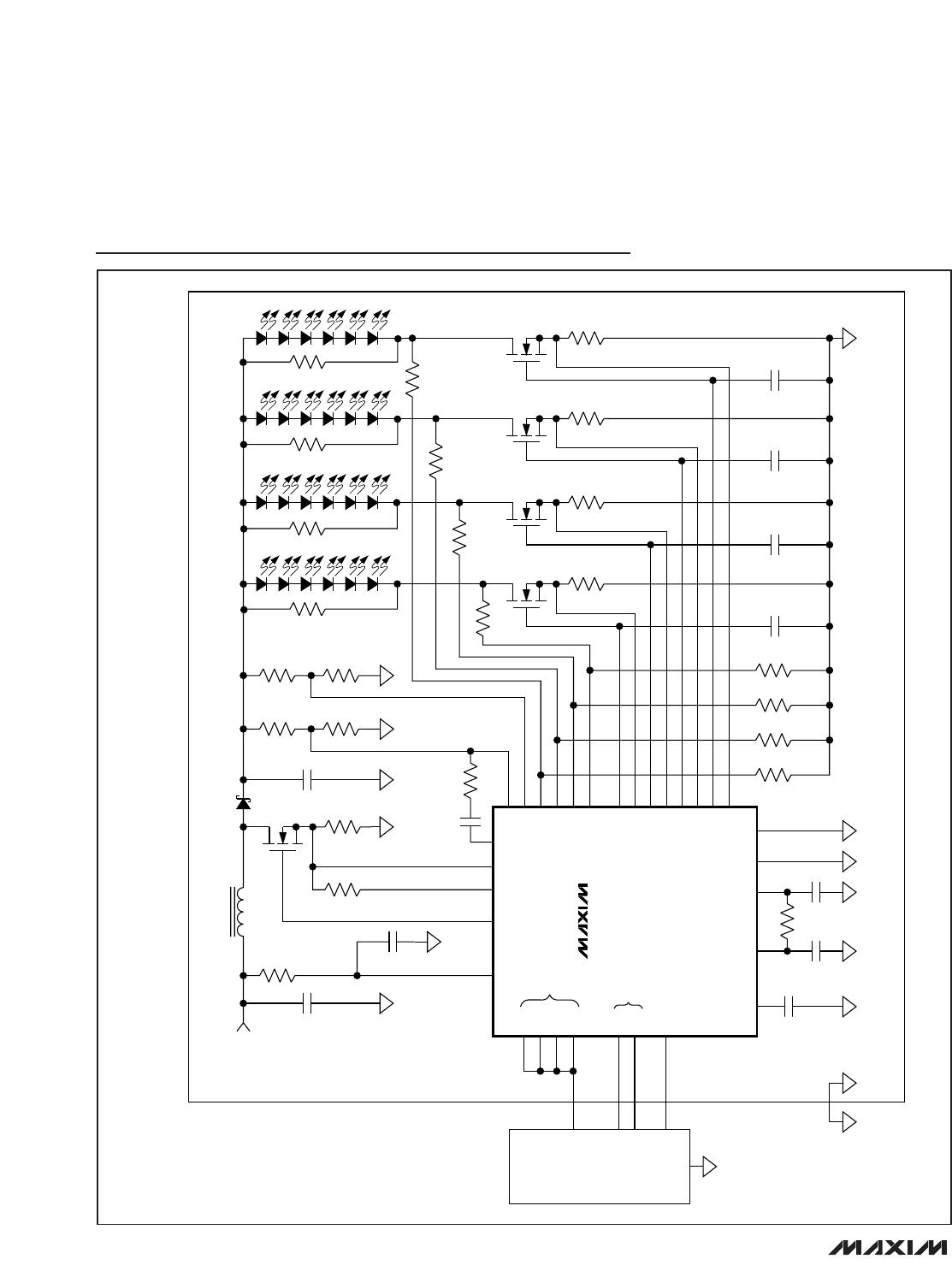
• Refer to the MAX16826 Evaluation Kit for an exam-
ple of proper board layout.
MAX16826
Programmable, Four-String HB LED Driver with
Output-Voltage Optimization and Fault Detection
______________________________________________________________________________________ 23