MAX16826
Programmable, Four-String HB LED Driver with
Output-Voltage Optimization and Fault Detection
_______________________________________________________________________________________ 9
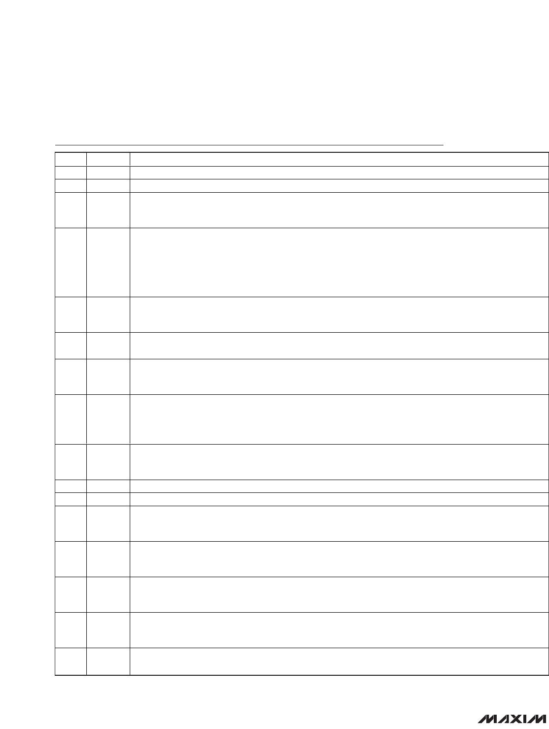
Pin Description (continued)
PIN NAME FUNCTION
18 DL1
LE D S tr i ng 1 Li near C ur r ent S our ce O utp ut. D L1 d r i ves the g ate of the exter nal FE T on LE D S tr i ng 1 and has
ap p r oxi m atel y 15m A sour ce/si nk cap ab i l i ty. C onnect a m i ni m um cap aci tor of 4700p F fr om D L1 to G N D to
com p ensate the i nter nal tr anscond uctance am p l i fi er as w el l as p r og r am the r i se and fal l ti m es of the LE D cur r ents.
19 DR1
LED String 1 External FET Drain Voltage Sense. The internal ADC uses this input to measure the drain to GND
voltage of the current sink FET. Drain voltage measurement information can be read back from the I
2
C
interface. Connect a voltage-divider to scale drain voltage as necessary.
20 CS2
LED String 2 Current-Sense Input. CS2 is regulated to a value set by an internal register. The regulation voltage
can be set between 97mV and 316mV.
21 DL2
LED String 2 Linear Current Source Output. DL2 drives the gate of the external FET on LED String 2 and has
approximately 15mA source/sink capability. Connect a minimum capacitor of 4700pF from DL2 to GND to
compensate the internal transconductance amplifier, as well as program the rise and fall times of the LED
currents.
22 DR2
LED String 2 External FET Drain Voltage Sense. The internal ADC uses this input to measure the drain to GND
voltage of the current sink FET. Drain voltage measurement information can be read back from the I
2
C
interface. Connect a voltage-divider to scale drain voltage as necessary.
23 CS3
LED String 3 Current-Sense Input. CS3 is regulated to a value set by an internal register. The regulation voltage
can be set between 97mV and 316mV.
24 DL3
LE D S tr i ng 3 Li near C ur r ent S our ce O utp ut. D L3 d r i ves the g ate of the exter nal FE T on LE D S tr i ng 3 and has
ap p r oxi m atel y 15m A sour ce/si nk cap ab i l i ty. C onnect a m i ni m um cap aci tor of 4700p F fr om D L3 to G N D to
com p ensate the i nter nal tr anscond uctance am p l i fi er , as w el l as p r og r am the r i se and fal l ti m es of the LE D cur r ents.
25 DR3
LED String 3 External FET Drain Voltage Sense. The internal ADC uses this input to measure the drain to GND
voltage of the current sink FET. Drain voltage measurement information can be read back from the I
2
C
interface. Connect a voltage-divider to scale drain voltage as necessary.
26 CS4
LED String 4 Current-Sense Input. CS4 is regulated to a value set by an internal register. The regulation voltage
can be set between 97mV and 316mV.
27 DL4
LE D S tr i ng 4 Li near C ur r ent S our ce O utp ut. D L3 d r i ves the g ate of the exter nal FE T on LE D S tr i ng 4 and has
ap p r oxi m atel y 15m A sour ce/si nk cap ab i l i ty. C onnect a m i ni m um cap aci tor of 4700p F fr om D L4 to G N D to
com p ensate the i nter nal tr anscond uctance am p l i fi er , as w el l as p r og r am the r i se and fal l ti m es of the LE D cur r ents.
28 DR4
LED String 4 External FET Drain Voltage Sense. The internal ADC uses this input to measure the drain to GND
voltage of the current sink FET. Drain voltage measurement information can be read back from the I
2
C
interface. Connect a voltage-divider to scale drain voltage as necessary.
29 IN
Power Supply. IN is internally connected to a 26V shunt regulator that sinks current. In conjunction with an
external resistor it allows time-limited load dump events as high as 40V to be safely handled by the IC. Bypass
IN to GND with a minimum 10μF capacitor.
30 CS Current-Sense Input
31 V
CC
Gate Driver Regulator Output. Bypass V
CC
to GND with a minimum 4.7μF ceramic capacitor. Gate drive current
pulses come from the capacitor connected to V
CC
. Place the capacitor as close as possible to V
CC
. If IN is
powered by a voltage less than 5.5V, connect V
CC
directly to IN.
32 DL Switching Regulator Gate Driver Output
—EP
Exposed Pad. Connect the exposed pad to the ground plane for heatsinking. Do not use this pad as the only
ground connection to the IC.