PCA9555 All information provided in this document is subject to legal disclaimers. © NXP Semiconductors N.V. 2017. All rights reserved.
Product data sheet Rev. 10 — 8 November 2017 4 of 34
NXP Semiconductors
PCA9555
16-bit I
2
C-bus and SMBus I/O port with interrupt
Fig 3. Pin configuration for SSOP24 Fig 4. Pin configuration for TSSOP24
Fig 5. Pin configuration for HVQFN24 Fig 6. Pin configuration for HWQFN24
INT
A1
A2
IO0_0
IO0_1
IO0_2
IO0_3
IO0_4
IO0_5
IO0_6
IO0_7
V
SS
PCA9555DB
002aac699
1
2
3
4
5
6
7
8
9
10
11
12
14
13
16
15
18
17
20
19
22
21
24
23
V
DD
SDA
SCL
A0
IO1_7
IO1_6
IO1_5
IO1_4
IO1_3
IO1_2
IO1_1
IO1_0
V
DD
SDA
SCL
A0
IO1_7
IO1_6
IO1_5
IO1_4
IO1_3
IO1_2
IO1_1
IO1_0
INT
A1
A2
IO0_0
IO0_1
IO0_2
IO0_3
IO0_4
IO0_5
IO0_6
IO0_7
V
SS
PCA9555PW
002aac700
1
2
3
4
5
6
7
8
9
10
11
12
14
13
16
15
18
17
20
19
22
21
24
23
002aac701
PCA9555BS
Transparent top view
IO1_3
IO0_4
IO0_5
IO1_4
IO0_3 IO1_5
IO0_2 IO1_6
IO0_1 IO1_7
IO0_0 A0
IO0_6
IO0_7
V
SS
IO1_0
IO1_1
IO1_2
A2
A1
V
DD
SDA
SCL
terminal 1
index area
6
13
5
14
4 15
3 16
2 17
1
18
7
8
9
10
11
12
24
23
22
21
20
19
INT
002aac881
Transparent top view
IO1_3
IO0_4
IO0_5
IO1_4
IO0_3 IO1_5
IO0_2 IO1_6
IO0_1 IO1_7
IO0_0 A0
IO0_6
IO0_7
V
SS
IO1_0
IO1_1
IO1_2
A2
A1
INT
V
DD
SDA
SCL
terminal 1
index area
6
13
5
14
4 15
3 16
2 17
1
18
7
8
9
10
11
12
24
23
22
21
20
19
PCA9555HF
PCA9555 All information provided in this document is subject to legal disclaimers. © NXP Semiconductors N.V. 2017. All rights reserved.
Product data sheet Rev. 10 — 8 November 2017 5 of 34
NXP Semiconductors
PCA9555
16-bit I
2
C-bus and SMBus I/O port with interrupt
5.2 Pin description
[1] HVQFN and HWQFN package die supply ground is connected to both the V
SS
pin and the exposed center
pad. The V
SS
pin must be connected to supply ground for proper device operation. For enhanced thermal,
electrical, and board-level performance, the exposed pad needs to be soldered to the board using a
corresponding thermal pad on the board, and for proper heat conduction through the board thermal vias
need to be incorporated in the PCB in the thermal pad region.
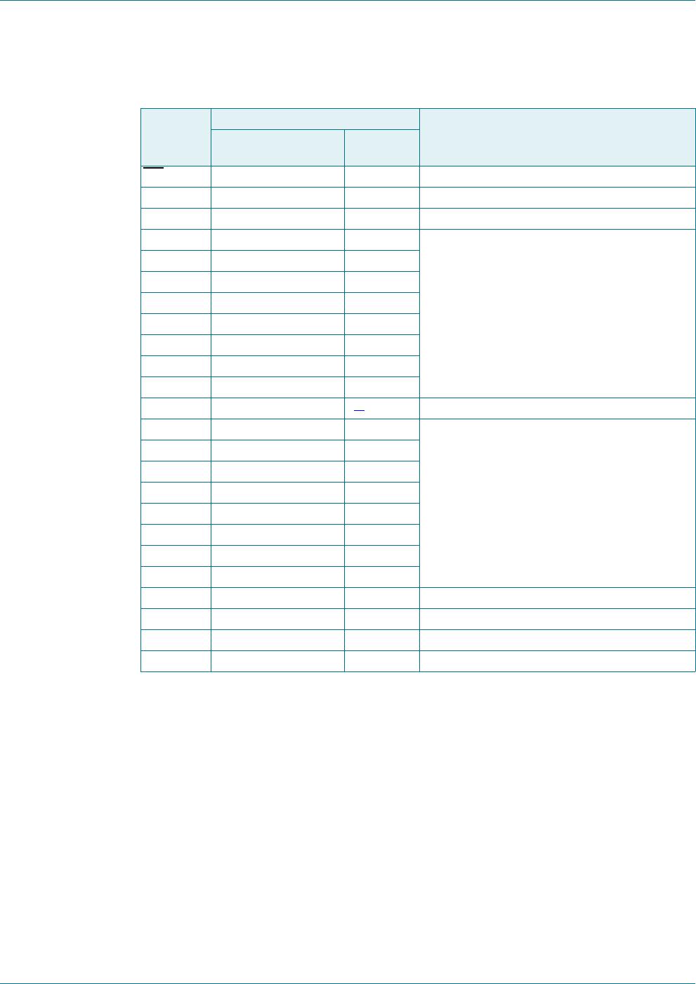
Table 3. Pin description
Symbol Pin Description
SO24, SSOP24,
TSSOP24
HVQFN24,
HWQFN24
INT
1 22 interrupt output (open-drain)
A1 2 23 address input 1
A2 3 24 address input 2
IO0_0 4 1 port 0 input/output
IO0_1 5 2
IO0_2 6 3
IO0_3 7 4
IO0_4 8 5
IO0_5 9 6
IO0_6 10 7
IO0_7 11 8
V
SS
12 9
[1]
supply ground
IO1_0 13 10 port 1 input/output
IO1_1 14 11
IO1_2 15 12
IO1_3 16 13
IO1_4 17 14
IO1_5 18 15
IO1_6 19 16
IO1_7 20 17
A0 21 18 address input 0
SCL 22 19 serial clock line
SDA 23 20 serial data line
V
DD
24 21 supply voltage
PCA9555 All information provided in this document is subject to legal disclaimers. © NXP Semiconductors N.V. 2017. All rights reserved.
Product data sheet Rev. 10 — 8 November 2017 6 of 34
NXP Semiconductors
PCA9555
16-bit I
2
C-bus and SMBus I/O port with interrupt
6. Functional description
Refer to Figure 1 “Block diagram of PCA9555.
6.1 Device address
6.2 Registers
6.2.1 Command byte
The command byte is the first byte to follow the address byte during a write transmission.
It is used as a pointer to determine which of the following registers will be written or read.
Fig 7. PCA9555 device address
R/W
002aac219
0 1 0 0 A2 A1 A0
programmable
slave address
fixed
Table 4. Command byte
Command Register
0 Input port 0
1 Input port 1
2 Output port 0
3 Output port 1
4 Polarity Inversion port 0
5 Polarity Inversion port 1
6 Configuration port 0
7 Configuration port 1

PCA9555PW,118

Mfr. #:
Manufacturer:
NXP Semiconductors
Description:
Interface - I/O Expanders 16-BIT I2C FM TP GPIO INT PU
Lifecycle:
New from this manufacturer.
Delivery:
DHL FedEx Ups TNT EMS
Payment:
T/T Paypal Visa MoneyGram Western Union