PCA9555 All information provided in this document is subject to legal disclaimers. © NXP Semiconductors N.V. 2017. All rights reserved.
Product data sheet Rev. 10 — 8 November 2017 7 of 34
NXP Semiconductors
PCA9555
16-bit I
2
C-bus and SMBus I/O port with interrupt
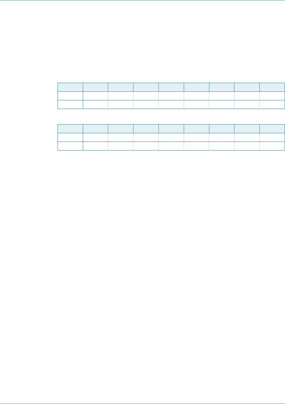
6.2.2 Registers 0 and 1: Input port registers
This register is an input-only port. It reflects the incoming logic levels of the pins,
regardless of whether the pin is defined as an input or an output by Register 3. Writes to
this register have no effect.
The default value ‘X’ is determined by the externally applied logic level.
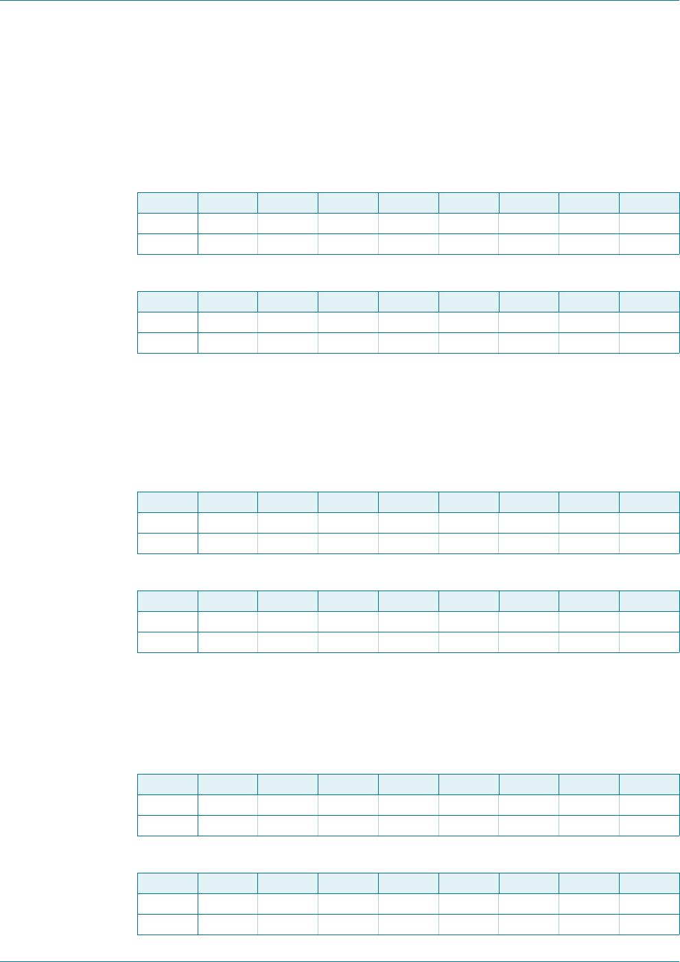
6.2.3 Registers 2 and 3: Output port registers
This register is an output-only port. It reflects the outgoing logic levels of the pins defined
as outputs by Registers 6 and 7. Bit values in this register have no effect on pins defined
as inputs. In turn, reads from this register reflect the value that is in the flip-flop controlling
the output selection, not the actual pin value.
6.2.4 Registers 4 and 5: Polarity Inversion registers
This register allows the user to invert the polarity of the Input port register data. If a bit in
this register is set (written with ‘1’), the Input port data polarity is inverted. If a bit in this
register is cleared (written with a ‘0’), the Input port data polarity is retained.
Table 5. Input port 0 Register
Bit 7 6 5 4 3 2 1 0
Symbol I0.7 I0.6 I0.5 I0.4 I0.3 I0.2 I0.1 I0.0
Default XXXXXXXX
Table 6. Input port 1 register
Bit 7 6 5 4 3 2 1 0
Symbol I1.7 I1.6 I1.5 I1.4 I1.3 I1.2 I1.1 I1.0
Default XXXXXXXX
Table 7. Output port 0 register
Bit 7 6 5 4 3 2 1 0
Symbol O0.7 O0.6 O0.5 O0.4 O0.3 O0.2 O0.1 O0.0
Default 11111111
Table 8. Output port 1 register
Bit 7 6 5 4 3 2 1 0
Symbol O1.7 O1.6 O1.5 O1.4 O1.3 O1.2 O1.1 O1.0
Default 11111111
Table 9. Polarity Inversion port 0 register
Bit 7 6 5 4 3 2 1 0
Symbol N0.7 N0.6 N0.5 N0.4 N0.3 N0.2 N0.1 N0.0
Default 00000000
Table 10. Polarity Inversion port 1 register
Bit 7 6 5 4 3 2 1 0
Symbol N1.7 N1.6 N1.5 N1.4 N1.3 N1.2 N1.1 N1.0
Default 00000000
PCA9555 All information provided in this document is subject to legal disclaimers. © NXP Semiconductors N.V. 2017. All rights reserved.
Product data sheet Rev. 10 — 8 November 2017 8 of 34
NXP Semiconductors
PCA9555
16-bit I
2
C-bus and SMBus I/O port with interrupt
6.2.5 Registers 6 and 7: Configuration registers
This register configures the directions of the I/O pins. If a bit in this register is set (written
with ‘1’), the corresponding port pin is enabled as an input with high-impedance output
driver. If a bit in this register is cleared (written with ‘0’), the corresponding port pin is
enabled as an output. Note that there is a high value resistor tied to V
DD
at each pin. At
reset, the device's ports are inputs with a pull-up to V
DD
.
6.3 Power-on reset
When power is applied to V
DD
, an internal power-on reset holds the PCA9555 in a reset
condition until V
DD
has reached V
POR
. At that point, the reset condition is released and the
PCA9555 registers and SMBus state machine will initialize to their default states. The
power-on reset typically completes the reset and enables the part by the time the power
supply is above V
POR
. However, when it is required to reset the part by lowering the power
supply, it is necessary to lower it below 0.2 V.
6.4 I/O port
When an I/O is configured as an input, FETs Q1 and Q2 are off, creating a
high-impedance input with a weak pull-up to V
DD
. The input voltage may be raised above
V
DD
to a maximum of 5.5 V.
If the I/O is configured as an output, then either Q1 or Q2 is on, depending on the state of
the Output Port register. Care should be exercised if an external voltage is applied to an
I/O configured as an output because of the low-impedance path that exists between the
pin and either V
DD
or V
SS
.
Table 11. Configuration port 0 register
Bit 7 6 5 4 3 2 1 0
Symbol C0.7 C0.6 C0.5 C0.4 C0.3 C0.2 C0.1 C0.0
Default 11111111
Table 12. Configuration port 1 register
Bit 7 6 5 4 3 2 1 0
Symbol C1.7 C1.6 C1.5 C1.4 C1.3 C1.2 C1.1 C1.0
Default 11111111
PCA9555 All information provided in this document is subject to legal disclaimers. © NXP Semiconductors N.V. 2017. All rights reserved.
Product data sheet Rev. 10 — 8 November 2017 9 of 34
NXP Semiconductors
PCA9555
16-bit I
2
C-bus and SMBus I/O port with interrupt
6.5 Bus transactions
6.5.1 Writing to the port registers
Data is transmitted to the PCA9555 by sending the device address and setting the least
significant bit to a logic 0 (see Figure 7 “
PCA9555 device address). The command byte is
sent after the address and determines which register will receive the data following the
command byte.
The eight registers within the PCA9555 are configured to operate as four register pairs.
The four pairs are Input Ports, Output Ports, Polarity Inversion Ports, and Configuration
Ports. After sending data to one register, the next data byte will be sent to the other
register in the pair (see Figure 9
and Figure 10). For example, if the first byte is sent to
Output Port 1 (register 3), then the next byte will be stored in Output Port 0 (register 2).
There is no limitation on the number of data bytes sent in one write transmission. In this
way, each 8-bit register may be updated independently of the other registers.
At power-on reset, all registers return to default values.
Fig 8. Simplified schematic of I/Os

PCA9555PW,118

Mfr. #:
Manufacturer:
NXP Semiconductors
Description:
Interface - I/O Expanders 16-BIT I2C FM TP GPIO INT PU
Lifecycle:
New from this manufacturer.
Delivery:
DHL FedEx Ups TNT EMS
Payment:
T/T Paypal Visa MoneyGram Western Union