LTC2655
9
2655f
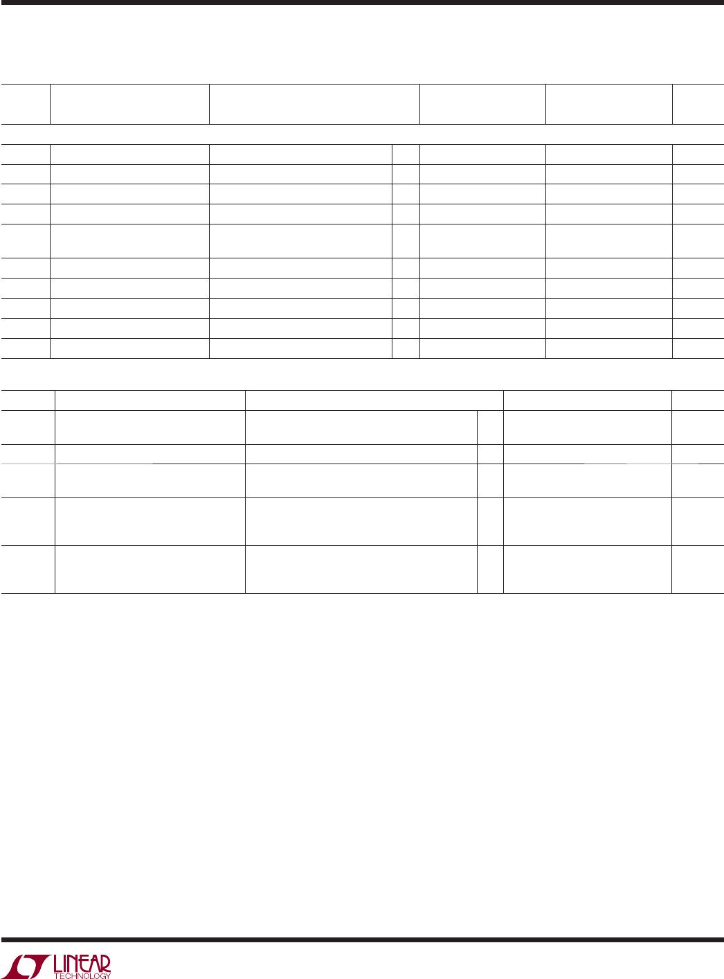
ELECTRICAL CHARACTERISTICS
LTC2655B-L16/LTC2655-L12/LTC2655B-H16/LTC2655-H12
SYMBOL PARAMETER CONDITIONS MIN TYP MAX UNITS
AC Performance
t
s
Settling Time ( Note 10) ±0.024%(±1LSB at 12 Bits)
±0.0015%(±1LSB at 16 Bits)
3.9
9.1
µs
µs
Settling Time for 1LSB Step ±0.024%(±1LSB at 12 Bits)
±0.0015%(±1LSB at 16 Bits)
2.4
4.5
µs
µs
Voltage Output Slew Rate 1.8 V/µs
Capacitive Load Driving 1000 pF
Glitch Impulse (Note 11) At Mid-Scale Transition, -L Option 4 nV•s
At Mid-Scale Transition, -H Option 7 nV•s
DAC to DAC Crosstalk (Note 12) C
REFCOMP
= C
REFIN/OUT
= 0.22µF 0.5 nV•s
Multiplying Bandwidth 150 kHz
e
n
Output Voltage Noise Density At f = 1kHz
At f = 10kHz
85
80
nV/√Hz
nV/√Hz
Output Voltage Noise 0.1Hz to 10Hz, Internal Reference (-L Options)
0.1Hz to 10Hz, Internal Reference (-H Options)
0.1Hz to 200KHz, Internal Reference (-L Options)
0.1Hz to 200KHz, Internal Reference (-H Options)
8
12
400
450
µV
P-P
µV
P-P
µV
P-P
µV
P-P
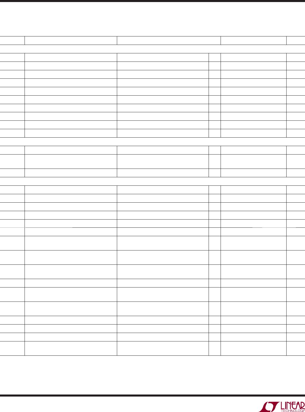
TIMING CHARACTERISTICS
The l denotes the specifi cations which apply over the full operating temperature
range, otherwise specifi cations are at T
A
= 25°C. V
CC
= 2.7V to 5.5V (LTC2655B-L16/LTC2655-L12), V
CC
= 4.5V to 5.5V (LTC2655B-H16,
LTC2655-H12), V
OUT
unloaded unless otherwise specifi ed.
LTC2655B-L16/LTC2655-L12/LTC2655B-H16/LTC2655-H12 (see Figure 1)
SYMBOL PARAMETER CONDITIONS MIN TYP MAX UNITS
f
SCL
SCL Clock Frequency
l
0 400 kHz
t
HD(STA)
Hold Time (Repeated) Start Condition
l
0.6 µs
t
LOW
Low Period of the SCL Clock Pin
l
1.3 µs
t
HIGH
High Period of the SCL Clock Pin
l
0.6 µs
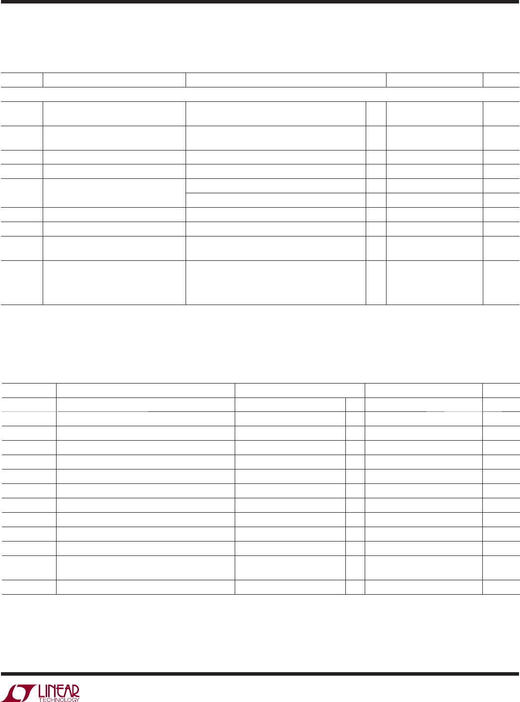
t
SU(STA)
Set-Up Time for a Repeated Start Program
l
0.6 µs
t
HD(DAT)
Data Hold Time
l
0 0.9 µs
t
SU(DAT)
Data Set-Up Time
l
100 ns
tr Rise Time of Both SDA and SCL Signals (Note 13)
l
20+0.1C
B
300 ns
tf Fall Time of Both SDA and SCL Signals (Note 13)
l
20+0.1C
B
300 ns
t
SU(STO)
Set-Up Time for Stop Condition
l
0.6 µs
t
BUF
Bus Free Time Between a Stop and Start Condition
l
1.3 µs
t1 Falling edge of the 9th Clock of the 3rd Input Byte
to LDAC High or Low Transition
l
400 ns
t2 LDAC Low Pulse Width
l
20 ns
The l denotes the specifi cations which apply over the full operating
temperature range, otherwise specifi cations are at T
A
= 25°C. V
CC
= 2.7V to 5.5V (LTC2655B-L16/LTC2655-L12), V
CC
= 4.5V to 5.5V
(LTC2655B-H16, LTC2655-H12), V
OUT
unloaded unless otherwise specifi ed.