AD7859/AD7859L
REV. A
–18–
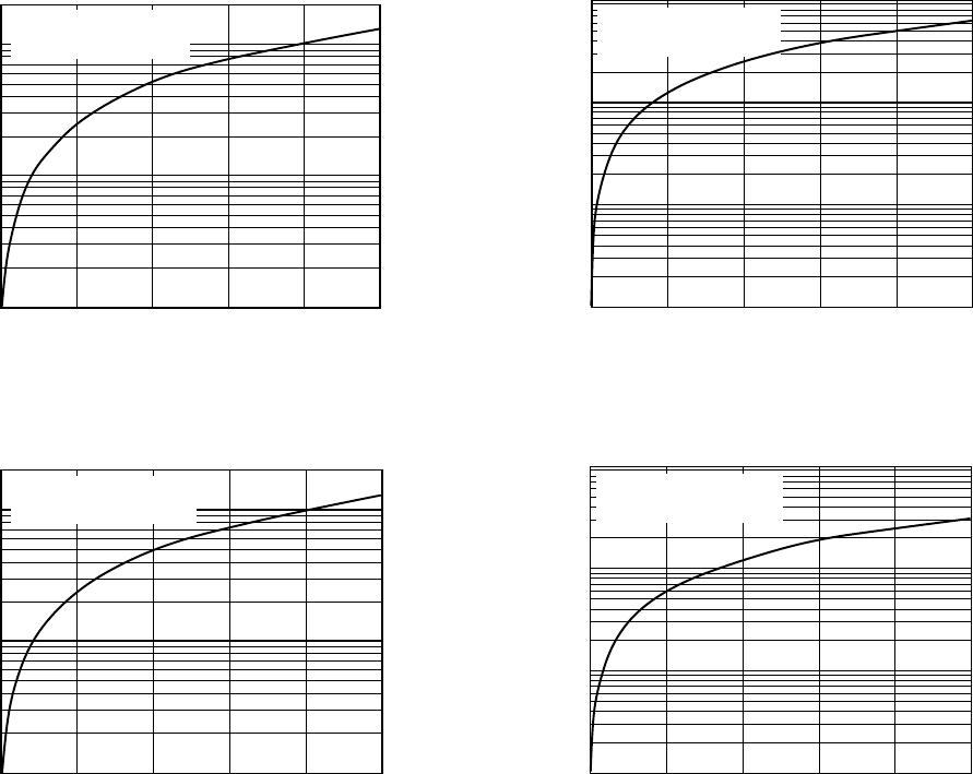
PSRR – dB
INPUT FREQUENCY – kHz
–78
–80
–88
0 10020 40 60 80
–82
–84
–86
AV
DD
= DV
DD
= 3.3V/5.0V
100mV pk-pk SINEWAVE ON AV
DD
–90
3.3V
5.0V
Figure 20. PSRR vs. Frequency
POWER-DOWN OPTIONS
The AD7859/AD7859L provides flexible power management to
allow the user to achieve the best power performance for a given
throughput rate. The power management options are selected
by programming the power management bits, PMGT1 and
PMGT0, in the control register and by use of the
SLEEP pin.
Table VII summarizes the power-down options that are avail-
able and how they can be selected by using either software,
hardware or a combination of both. The AD7859/AD7859L can
be fully or partially powered down. When fully powered down,
all the on-chip circuitry is powered down and I
DD
is 10 µA typ.
If a partial power-down is selected, then all the on-chip circuitry
except the reference is powered down and I
DD
is 400 µA typ.
The choice of full or partial power-down does not give any sig-
nificant improvement in throughput with a power-down between
conversions. This is discussed in the next section—Power-Up
Times. But a partial power-down does allow the on-chip refer-
ence to be used externally even though the rest of the AD7859/
AD7859L circuitry is powered down. It also allows the
AD7859/AD7859L to be powered up faster after a long power-
down period when using the on-chip reference (See Power-Up
Times—Using On-Chip Reference).
When using the
SLEEP pin, the power management bits
PMGT1 and PMGT0 should be set to zero. Bringing the
SLEEP pin logic high ensures normal operation, and the part
does not power down at any stage. This may be necessary if the
part is being used at high throughput rates when it is not pos-
sible to power down between conversions. If the user wishes to
power down between conversions at lower throughput rates
(i.e., <100 kSPS for the AD7859 and <60 kSPS for the
AD7859L) to achieve better power performances, then the
SLEEP pin should be tied logic low.
If the power-down options are to be selected in software only,
then the
SLEEP pin should be tied logic high. By setting the
power management bits PMGT1 and PMGT0 as shown in
Table VII, a Full Power-Down, Full Power-Up, Full Power-
Down Between Conversions, and a Partial Power-Down Be-
tween Conversions can be selected.
A combination of hardware and software selection can also be
used to achieve the desired effect.
Table VII. Power Management Options
PMGT1 PMGT0 SLEEP
Bit Bit Pin Comment
0 0 0 Full Power-Down Between
Conversions (HW / SW)
0 0 1 Full Power-Up (HW / SW)
0 1 X Full Power-Down Between
Conversions (SW )
1 0 X Full Power-Down (SW)
1 1 X Partial Power-Down Between
Conversions (SW)
NOTE
SW = Software selection, HW = Hardware selection.
POWER-UP TIMES
Using An External Reference
When the AD7859/AD7859L are powered up, the parts are
powered up from one of two conditions. First, when the power
supplies are initially powered up and, secondly, when the parts
are powered up from either a hardware or software power-down
(see last section).
When AV
DD
and DV
DD
are powered up, the AD7859/AD7859L
enters a mode whereby the CONVST signal initiates a timeout
followed by a self-calibration. The total time taken for this time-
out and calibration is approximately 70 ms—see Calibration on
Power-Up in the calibration section of this data sheet. During
power-up the functionality of the
SLEEP pin is disabled, i.e.,
the part will not power down until the end of the calibration if
SLEEP is tied logic low. The power-up calibration mode can be
disabled if the user writes to the control register before a
CONVST signal is applied. If the time out and self-calibration
are disabled, then the user must take into account the time
required by the AD7859/AD7859L to power up before a self-
calibration is carried out. This power-up time is the time taken
for the AD7859/AD7859L to power up when power is first
applied (300 µs typ) or the time it takes the external reference to
settle to the 12-bit level—whichever is the longer.
The AD7859/AD7859L powers up from a full hardware or soft-
ware power-down in 5 µs typ. This limits the throughput which
the part is capable of to 100 kSPS for the AD7859 and 60 kSPS
for the AD7859L when powering down between conversions.
Figure 21 shows how power-down between conversions is
implemented using the
CONVST pin. The user first selects the
power-down between conversions option by using the
SLEEP
pin and the power management bits, PMGT1 and PMGT0, in
the control register. See last section. In this mode the AD7859/
AD7859L automatically enters a full power-down at the end of
a conversion, i.e., when BUSY goes low. The falling edge of the
next
CONVST pulse causes the part to power up. Assuming the
external reference is left powered up, the AD7859/AD7859L
should be ready for normal operation 5 µs after this falling edge.
The rising edge of
CONVST initiates a conversion so the
CONVST pulse should be at least 5 µs wide. The part automati-
cally powers down on completion of the conversion. Where the
software convert start is used, the part may be powered up in
software before a conversion is initiated.