Si4734/35-C40
Rev. 1.0 21
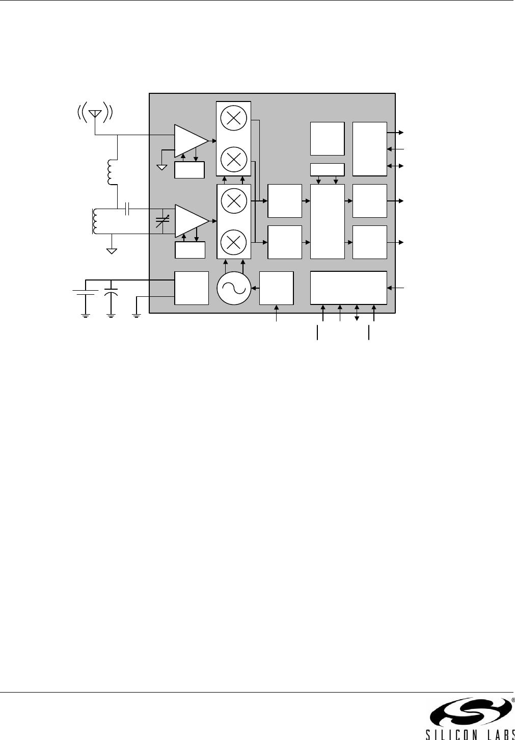
5.2. Operating Modes
The Si4734/35 operates in either an FM receive or an
AM/SW/LW receive mode. In FM mode, radio signals
are received on FMI and processed by the FM front-end
circuitry. In AM/SW/LW mode, radio signals are received
on AMI and processed by the AM front-end circuitry. In
addition to the receiver mode, there is a clocking mode
to choose to clock the Si4734/35 from a reference clock
or crystal. On the Si4735, there is an audio output mode
to choose between an analog and/or digital audio
output. In the analog audio output mode, ROUT and
LOUT are used for the audio output pins. In the digital
audio mode, DOUT, DFS, and DCLK pins are used.
Concurrent analog/digital audio output mode is also
available requiring all five pins. The receiver mode and
the audio output mode are set by the POWER_UP
command listed in Table 14, “Selected Si473x
Commands,” on page 27.
5.3. FM Receiver
The Si4734/35 FM receiver is based on the proven
Si4700/01 FM tuner. The receiver uses a digital low-IF
architecture allowing the elimination of external
components and factory adjustments. The Si4734/35
integrates a low noise amplifier (LNA) supporting the
worldwide FM broadcast band (64 to 108 MHz). An
AGC circuit controls the gain of the LNA to optimize
sensitivity and rejection of strong interferers. An image-
reject mixer downconverts the RF signal to low-IF. The
quadrature mixer output is amplified, filtered, and
digitized with high resolution analog-to-digital
converters (ADCs). This advanced architecture allows
the Si4734/35 to perform channel selection, FM
demodulation, and stereo audio processing to achieve
superior performance compared to traditional analog
architectures.
5.4. AM Receiver
The highly-integrated Si4734/35 supports worldwide AM
band reception from 520 to 1710 kHz using a digital
low-IF architecture with a minimum number of external
components and no manual alignment required. This
digital low-IF architecture allows for high-precision
filtering offering excellent selectivity and SNR with
minimum variation across the AM band. The DSP also
provides adjustable channel step sizes in 1 kHz
increments, AM demodulation, soft mute, seven
different channel bandwidth filters, and additional
features, such as a programmable automatic volume
control (AVC) maximum gain allowing users to adjust
the level of background noise. Similar to the FM
receiver, the integrated LNA and AGC optimize
sensitivity and rejection of strong interferers allowing
better reception of weak stations.
The Si4734/35 provides highly-accurate digital AM
tuning without factory adjustments. To offer maximum
flexibility, the receiver supports a wide range of ferrite
loop sticks from 180–450 µH. An air loop antenna is
supported by using a transformer to increase the
effective inductance from the air loop. Using a 1:5 turn
ratio inductor, the inductance is increased by 25 times
and easily supports all typical AM air loop antennas
which generally vary between 10 and 20 µH.
5.5. SW Receiver
The Si4734/35 is the first fully integrated IC to support
AM and FM, as well as short wave (SW) band reception
from 2.3 to 26.1 MHz fully covering the 120 meter to
11 meter bands. The Si4734/35 offers extensive
shortwave features such as continuous digital tuning
with minimal discrete components and no factory
adjustments. Other SW features include adjustable
channel step sizes in 1 kHz increments, adjustable
channel bandwidth settings, advanced seek algorithm,
and soft mute.
The Si4734/35 uses the FM antenna to capture short
wave signals. These signals are then fed directly into
the AMI pin in a wide band configuration. See “AN382:
Si4734/35 Designer’s Guide” for more details.
5.6. LW Receiver
The Si4734/35 supports the long wave (LW) band from
153 to 279 kHz. The highly integrated Si4734/35 offers
continuous digital tuning with minimal discrete
components and no factory adjustments. The Si4734/35
also offers adjustable channel step sizes in 1 kHz
increments, adjustable channel bandwidth settings,
advanced seek algorithm, and soft mute.
The Si4734/35 uses a separate ferrite bar antenna to
capture long wave signals.
5.7. Digital Audio Interface (Si4735 Only)
The digital audio interface operates in slave mode and
supports three different audio data formats:
I
2
S
Left-Justified
DSP Mode
5.7.1. Audio Data Formats
In I
2
S mode, by default the MSB is captured on the
second rising edge of DCLK following each DFS
transition. The remaining bits of the word are sent in
order, down to the LSB. The left channel is transferred
first when the DFS is low, and the right channel is
transferred when the DFS is high.
In Left-Justified mode, by default the MSB is captured
on the first rising edge of DCLK following each DFS
transition. The remaining bits of the word are sent in