Rev. 1.2 4/13 Copyright © 2013 by Silicon Laboratories Si8220/21
Si8220/21
0.5 AND 2.5 AMP ISODRIVERS WITH OPTO INPUT
(2.5, 3.75, AND 5.0 KV
RMS
)
Features
Applications
Safety Regulatory Approvals
Description
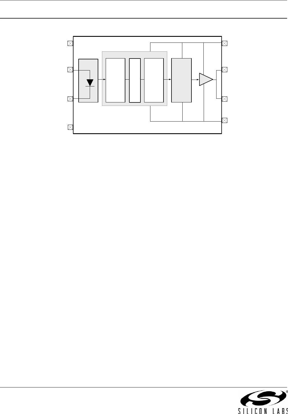
The Si8220/21 is a high-performance functional upgrade for opto-coupled
drivers, such as the HCPL-3120 and the HPCL-0302 providing 2.5 A of
peak output current. It utilizes Silicon Laboratories' proprietary silicon
isolation technology, which provides a choice of 2.5, 3.75, or 5.0 kV
RMS
withstand voltages per UL1577. This technology enables higher
performance, reduced variation with temperature and age, tighter part-to-
part matching, and superior common-mode rejection compared to opto-
isolated drivers. While the input circuit mimics the characteristics of an
LED, less drive current is required, resulting in increased efficiency.
Propagation delay time is independent of input drive current, resulting in
consistently short propagation time, tighter unit-to-unit variation, and
greater input circuit design flexibility.
Functional upgrade for HCPL-0302,
HCPL-3120, TLP350, and similar
opto-drivers
60 ns propagation delay max
(independent of input drive current)
14x tighter part-to-part matching
versus opto-drivers
2.5, 3.75, and 5.0 kV
RMS
isolation
Transient Immunity
30 kV/µs
Under-voltage lockout protection with
hysteresis
Resistant to temperature and aging
effects
Gate driver supply voltage
6.5 V to 24 V
Wide operating range
–40 to +125 °C
RoHS-compliant packages
SOIC-8 narrow body
SOIC-16 wide body
IGBT/ MOSFET gate drives
Industrial control systems
Switch mode power supplies
UPS systems
Motor control drives
Inverters
UL 1577 recognized
Up to 5000 Vrms for 1 minute
CSA component notice 5A
approval
IEC 60950-1, 61010-1, 60601-1
(reinforced insulation)
VDE certification conformity
IEC 60747-5-2 (VDE 0884 Part 2)
EN 60950-1 (reinforced insulation)
Patent pending
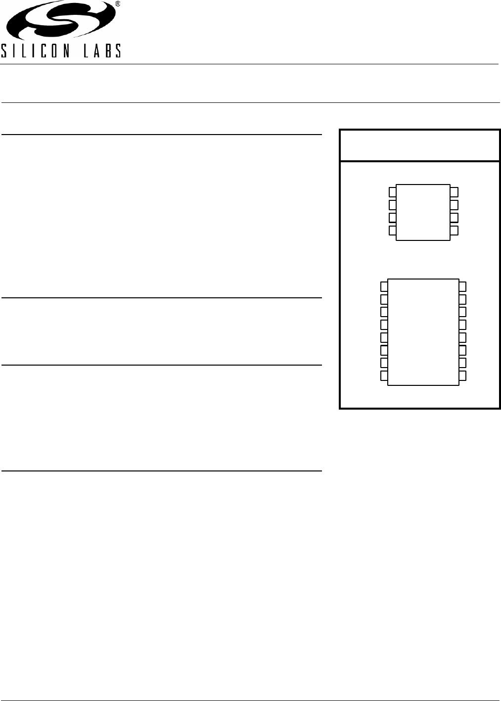
Pin Assignments:
See page 20
V
SS
V
DD
V
O
V
SS
CATHODE
ANODE
NC
1
2
3
4
5
6
7
8
Top View
NC
NC
9
12
11
10
13
14
15
16
NC
NC
NC
NC
NC
CATHODE
NC
NC
ANODE
NC
1
2
3
4
5
6
7
8
V
O
CATHODE
Narrow Body SOIC
Top View
V
SS
V
O
V
DD
Wide Body SOIC