AMIS30522, NCV70522
http://onsemi.com
10
TYPICAL APPLICATION SCHEMATIC
DIR
NXT
DO
DI
CLK
CLR
SLA
AMIS30522/
100 nF
100 nF 100 nF 100 nF
VDD
VBB
VBB
VCP
CPN
CPP
MOTXP
MOTXN
MOTYP
MOTYN
220 nF
R
3
R
2
C
4
C
2
C
3
C
6
C
7
M
C
5
TSTO
GND
C
8
R
1
+
C
1
CS
ERR
Figure 6. Typical Application Schematic AMIS30522/NCV70522
5
4
31
2
3
13
12
6
7
11
9
10
25,26
21,22
15,16
19,20
NCV70522
1,
8
17,
18
23,
24 30 29
32 14 27
mC
220 nF
100 mF
V
BAT
28
POR
/WD
R
4
D
1
Table 8. EXTERNAL COMPONENTS LIST AND DESCRIPTION
Component Function Typ. Value Tolerance Unit
C
1
V
BB
Buffer Capacitor (Low ESR < 1 W)
100 20 +80%
mF
C
2
, C
3
V
BB
Decoupling Block Capacitor 100 20 +80% nF
C
4
V
DD
Buffer Capacitor 220 $20% nF
C
5
V
DD
Buffer Capacitor 100 $20% nF
C
6
ChargePump Buffer Capacitor 220 $20% nF
C
7
ChargePump Pumping Capacitor 220 $20% nF
C
8
Low Pass Filter SLA 1 $20% nF
R
1
Low Pass Filter SLA 5.6 $1%
kW
R
2
, R
3
Pullup Resistor Open Drain Output 4.7 $1%
kW
D
1
Reverse Protection Diode MURD530
AMIS30522, NCV70522
http://onsemi.com
11
FUNCTIONAL DESCRIPTION
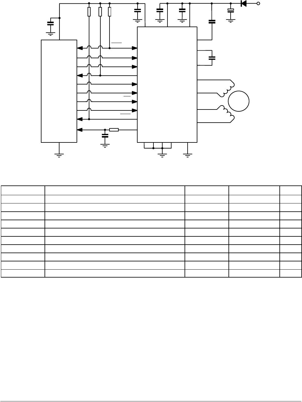
HBridge Drivers
A full Hbridge is integrated for each of the two stator
windings. Each Hbridge consists of two lowside and two
highside Ntype MOSFET switches. Writing logic ‘0’ in
bit <MOTEN> disables all drivers (HighImpedance).
Writing logic ‘1’ in this bit enables both bridges and current
can flow in the motor stator windings.
In order to avoid large currents through the Hbridge
switches, it is guaranteed that the top and bottom switches
of the same halfbridge are never conductive
simultaneously (interlock delay).
A twostage protection against shorts on motor lines is
implemented. In a first stage, the current in the driver is
limited. Secondly, when excessive voltage is sensed across
the transistor, the transistor is switchedoff.
In order to reduce the radiated/conducted emission,
voltage slope control is implemented in the output switches.
The output slope is defined by the gatedrain capacitance of
output transistor and the (limited) current that drives the
gate. There are two trimming bits for slope control (See
Table 12 SPI Control Parameter Overview EMC[1:0]).
The power transistors are equipped with socalled “active
diodes”: when a current is forced through the transistor
switch in the reverse direction, i.e. from source to drain, then
the transistor is switched on. This ensures that most of the
current flows through the channel of the transistor instead of
through the inherent parasitic drainbulk diode of the
transistor.
Depending on the desired current range and the
microstep position at hand, the R
DS(on)
of the lowside
transistors will be adapted such that excellent currentsense
accuracy is maintained. The R
DS(on)
of the highside
transistors remain unchanged, see also the DCparameter
table for more details.
PWM Current Control
A PWM comparator compares continuously the actual
winding current with the requested current and feeds back
the information to a digital regulation loop. This loop then
generates a PWM signal, which turns on/off the Hbridge
switches. The switching points of the PWM dutycycle are
synchronized to the onchip PWM clock.
The frequency of the PWM controller can be doubled to
reduce the overall currentripple with a factor of two.
To further reduce the emission, an artificial jitter can be
added to the PWM frequency. (see Table 12, SPI Control
Register 1). The PWM frequency will not vary with changes
in the supply voltage. Also variations in motorspeed or
loadconditions of the motor have no effect. There are no
external components required to adjust the PWM frequency.
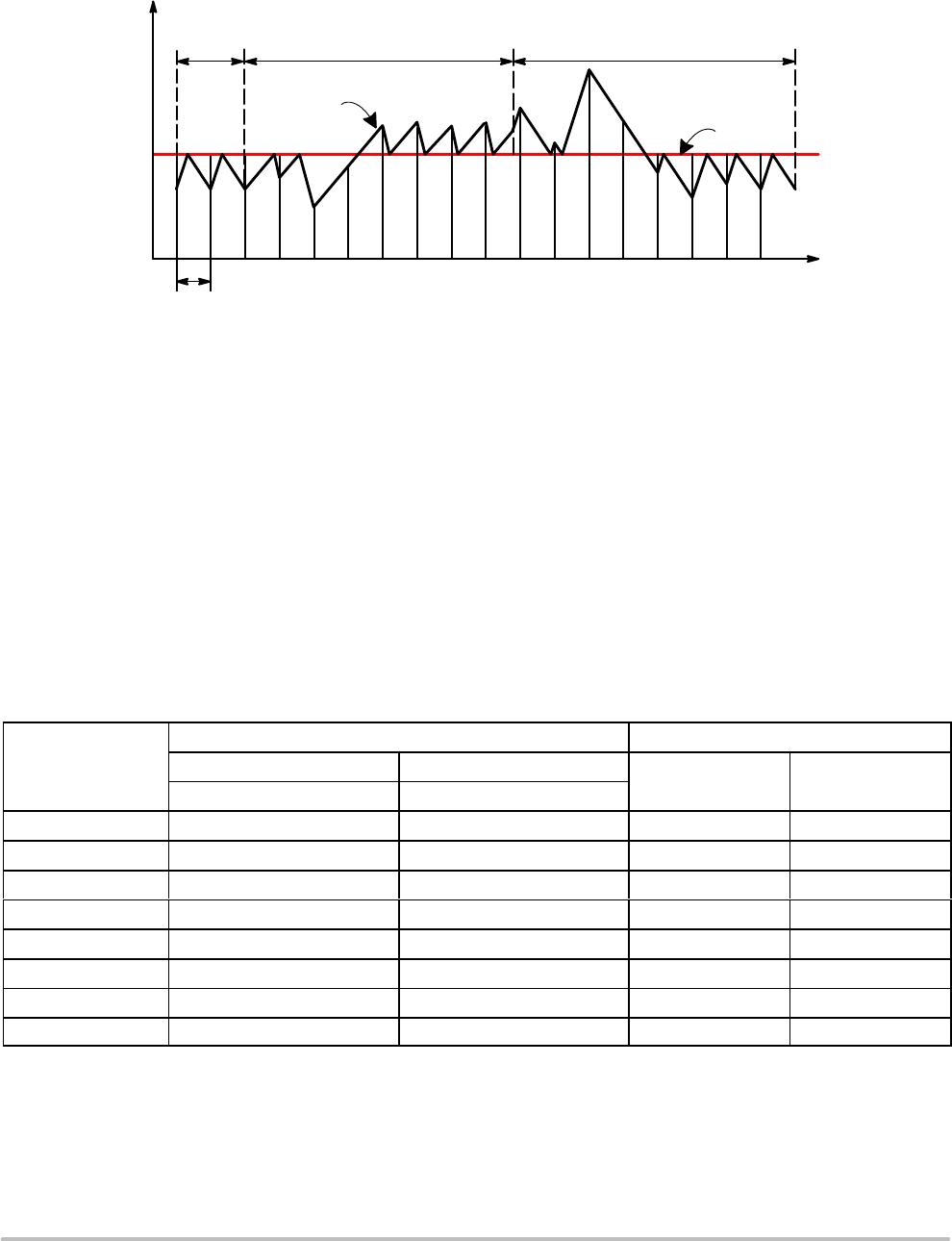
Automatic Forward & SlowFast Decay
The PWM generation is in steadystate using a
combination of forward and slowdecay. The absence of
fastdecay in this mode, guarantees the lowest possible
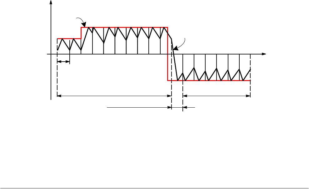
currentripple “by design”. For transients to lower current
levels, fastdecay is automatically activated to allow
highspeed response. The selection of fast or slow decay is
completely transparent for the user and no additional
parameters are required for operation.
Icoil
0 t
Forward & Slow Decay
Actual value
Set value
Figure 7. Forward & Slow/Fast Decay PWM
T
PWM
Forward & Slow Decay
Fast Decay & Forward
AMIS30522, NCV70522
http://onsemi.com
12
Automatic Duty Cycle Adaptation
In case the supply voltage is lower than 2*Bemf, then the
duty cycle of the PWM is adapted automatically to >50% to
maintain the requested average current in the coils. This
process is completely automatic and requires no additional
parameters for operation.
Actual value
Duty Cycle
< 50%
Duty Cycle < 50%
t
Icoil
Set value
Figure 8. Automatic Duty Cycle Adaptation
Duty Cycle > 50%
T
PWM
Step Translator
Step Mode
The Step Translator provides the control of the motor by
means of SPI register Stepmode: SM[2:0], SPI register
DIRCNTRL and input pins DIR and NXT. It is translating
consecutive steps in corresponding currents in both motor
coils for a given stepmode.
One out of 7 possible stepping modes can be selected
through SPIbits SM[2:0] (Table 12).
After poweron or hard reset, the coilcurrent translator
is set to the default 1/32 microstepping at position ‘0’.
Upon changing the Step Mode, the translator jumps to
position 0* of the corresponding stepping mode. When
remaining in the same Step Mode, subsequent translator
positions are all in the same column and increased or
decreased with 1. Table 10 lists the output current vs. the
translator position.
As shown in Figure 9 the output currentpairs can be
projected approximately on a circle in the (I
x
,I
y
) plane.
There are however two exceptions: uncompensated half step
and full step. In these stepmodes the currents are not
regulated to a fraction of I
max
but are in all intermediate steps
regulated at 100%. In the (I
x
,I
y
) plane the currentpairs are
projected on a square. Table 9 lists the output current vs. the
translator position for these cases.
Table 9. SQUARE TRANSLATOR TABLE FOR FULL STEP AND UNCOMPENSATED HALF STEP
MSP[6:0]
Stepmode ( SM[2:0] ) % of I
max
101 110
Coil x Coil y
Uncompensated HalfStep Full Step
000 0000 0* 0 100
001 0000 1 1 100 100
010 0000 2 100 0
011 0000 3 2 100 100
100 0000 4 0 100
101 0000 5 3 100 100
110 0000 6 100 0
111 0000 7 0 100 100

AMIS30522C5222G

Mfr. #:
Manufacturer:
ON Semiconductor
Description:
Motor / Motion / Ignition Controllers & Drivers 800MA STEPPER DRVR
Lifecycle:
New from this manufacturer.
Delivery:
DHL FedEx Ups TNT EMS
Payment:
T/T Paypal Visa MoneyGram Western Union

Products related to this Datasheet