AMIS−30522, NCV70522
http://onsemi.com
18
PWMsh
SLAT
SLA−Pin
last
retained
retain last sample
previous output is
buf
Ssh Sh
Ch
Csh
SLAT
NOT (Icoil=0)
Icoil=0
PWMsh
SLA−Pin
div2
div4
t
t
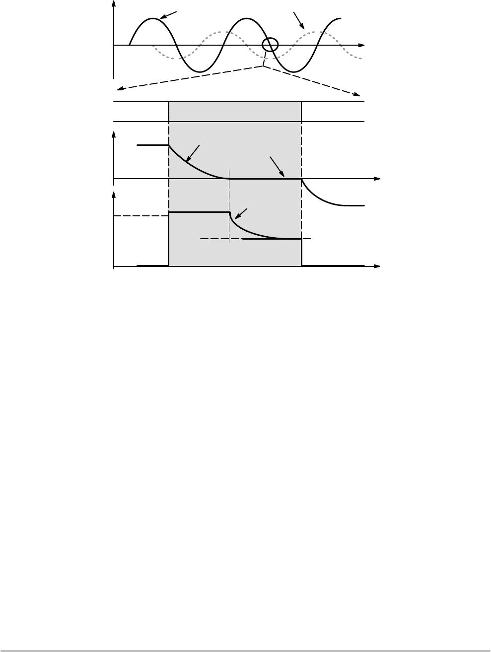
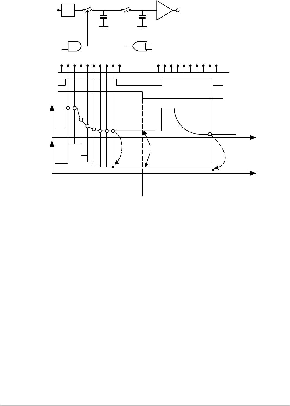
Figure 14. Timing Diagram of SLA−Pin
SLAT = 1 => SLA−pin is “transparent” during
V
BEMF
sampling @ Coil Current Zero
Crossing. SLA−pin is updated “real−time”.
SLAT = 0 => SLA−pin is not “transparent”
during V
BEMF
sampling @ Coil Current Zero
Crossing. SLA−pin is updated when leaving
current−less state.
V
COIL
V
COIL
V
BEMF
sample
is
kept at SLA pin
Icoil=0
Warning, Error Detection and Diagnostics Feedback
Thermal Warning and Shutdown
When Junction temperature rises above T
TW
, the thermal
warning bit <TW> is set (Table 16 SPI Status Register 0). If
junction temperature increases above thermal shutdown
level, then the circuit goes in “Thermal Shutdown” mode
(<TSD>) and all driver transistors are disabled (high
impedance) (Table 16 SPI Status Register 2). The conditions
to reset flag <TSD> is to be at a temperature lower than T
TW
and to clear the <TSD> flag by reading it using any SPI read
command.
Overcurrent Detection
The overcurrent detection circuit monitors the load
current in each activated output stage. If the load current
exceeds the overcurrent detection threshold, then the
overcurrent flag is set and the drivers are switched off to
reduce the power dissipation and to protect the integrated
circuit. Each driver transistor has an individual detection bit
in the Table 16 SPI Status Registers 1 and SPI Status
Register 2 (<OVCXij> and <OVCYij>). Error condition is
latched and the microcontroller needs to clear the status bits
to reactivate the drivers.
Note: Successive reading the SPI Status Registers 1 and 2 in
case of a short circuit condition, may lead to damage to the
drivers.
Open Coil Detection
Open coil detection is based on the observation of 100%
duty cycle of the PWM regulator. If in a coil 100% duty cycle
is detected for longer than 32 ms the appropriate status bit in
the SPI status register is set (<OPENX> or <OPENY>).
(Table 16: SPI Status Register 0).
When the resistance of a motor coil is very large and the
battery voltage is low, it can happen that the motor driver is
not able to deliver the requested current to the motor. Under
these conditions the PWM controller duty cycle will be
100% and after 32 ms, the error pin and <OPENX>,
<OPENY> will flag this situation (motor current is kept
alive). This feature can be used to test if the operating
conditions (supply voltage, motor coil resistance) still allow
reaching the requested coil−current or else the coil−current
should be reduced.